This guide will go through the components in your loaned or purchased Arduino kit, providing links to example code and projects, as well as to more in-depth, technical information about the sensors and actuators included in the kits. If you have further questions about any components, ask someone in the Hackspace in E110 for more info.
NB: Never solder anything directly to the components in loaned kits, remember to bend legs/leads properly, and always follow the markings on your specific sensor.
If you need a component fixed to a project, talk to Hackspace or Makerspace staff about options to achieve the desired effect without soldering the part directly.
components to sense data from the world around us and convert it into voltage for the Arduino to read.
The tilt sensor included with your kit provides an on/off (ie. digital) signal which can be read by one of the Arduino's digital pins. When upright, the Arduino should read on/true/1, while tilted any other way will provide off/false/0. See Adafruit's Reading Switch State with a Microcontroller example, which shows how to connect the sensor on your breadboard and provides code to debounce the signal to remove unwanted noise from the readings. For more info on debouncing, see this example on the Arduino website.
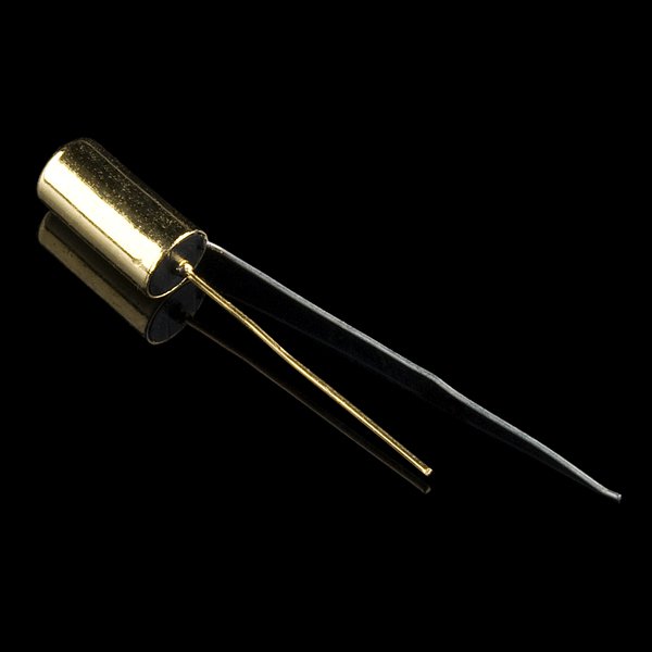

The temperature sensor included with your kit provides an analog value (0-1023) relative to the temperature around it. The output pin can be plugged directly into an analog input on your Arduino, where you can convert the reading in voltage into a temperature. See this Adafruit walkthrough, with included code, for how to convert the voltage to degrees celsius.
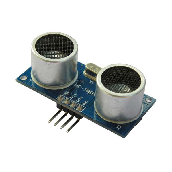
The ultrasonic proximity sensors in the kits rely on emitting a sound beyond the human hearing range and measuring how long it takes to bounce off whatever is in front of it to calculate how far away the object is. Depending on the code and the software you are using, these sensors can be a little quirky and fiddly in certain circumstances.
Many Arduino example projects make use of multiple instances of the delay() function to slow the Serial monitor, or adjust the speed of a Servo motor, for example. The delay() function halts all other functionality of the Arduino for the duration of time specified, and so it can lead to unpredictable behaviour from the sensor, which uses the time between sending a ping and receiving it back to calculate distance. The Ping example included with the Arduino software (File>Examples>Sensors>Ping) is a good starting point, but if your code utilises the delay() function elsewhere, it could lead to some crazy readings. If this is a problem for you, see this Adafruit guide on how to Ditch the delay().
These sensors are not supported in the CRL Arduino-Max Package.
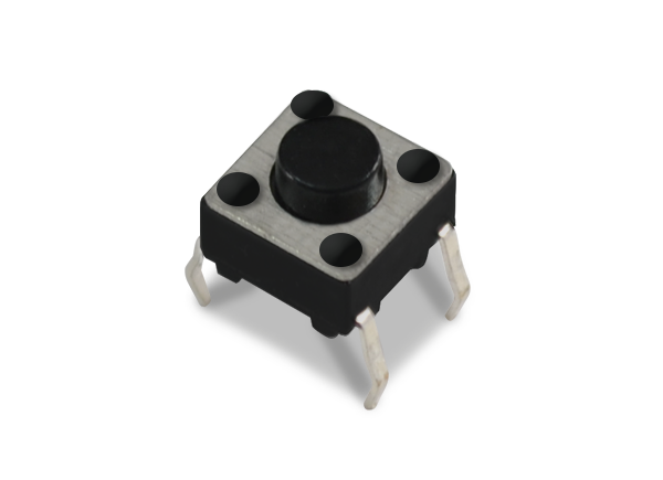
Push buttons are useful for triggering some sort of event in your code, turning components on and off, and so on. When pressed, the button connects two parts of your circuit which are otherwise separated. Occasionally the readings from these buttons can see some interference from various parts of your circuit and other electrical equipment, so if you are not getting consistent results, it is recommended to use a pullup resistor, which you can learn more about here. Also see this information on debouncing.
Potentiometers or pots are variable resistors with a knob to control the amount of resistance. See this basic Arduino example, using a potentiometer to control the speed at which an LED blinks.
Note that the potentiometer used in the Arduino example above is slightly different to the one in the image to the right. The potentiometer to the right has clearly marked pins for ground (G), voltage (V) and an S for sensor/signal, however, if your potentiometer looks more like the one in the linked example and has no markings, follow the circuit as it instructs.


This sensor has a small microphone which provides an analog signal (ranging from 0 to 1023) to your Arduino according to the loudness of sound it receives. It is not intended to be used to record sounds, but to use the amplitude of any given sound to control other elements within your Arduino sketch, like, for example, using a clap to trigger some lights. See some examples here.
You can carefully adjust the sensitivity of the sensor with a small screwdriver and the onboard trimmer. Be gentle to avoid stripping or damaging it.
Photoresistors change their resistance according to the amount of light they receive. See this Arduino example on how to use a photoresistor as an analog input.

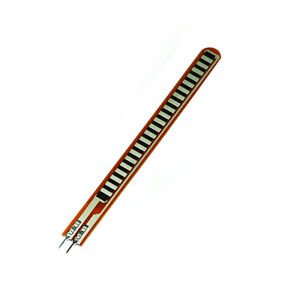
The flex sensor bends in one direction and increases its resistance as it bends. See this Instructables tutorial on how to wire it up and control the brightness of an LED.
components to convert numbers and voltage from the Arduino into something we can physically perceive
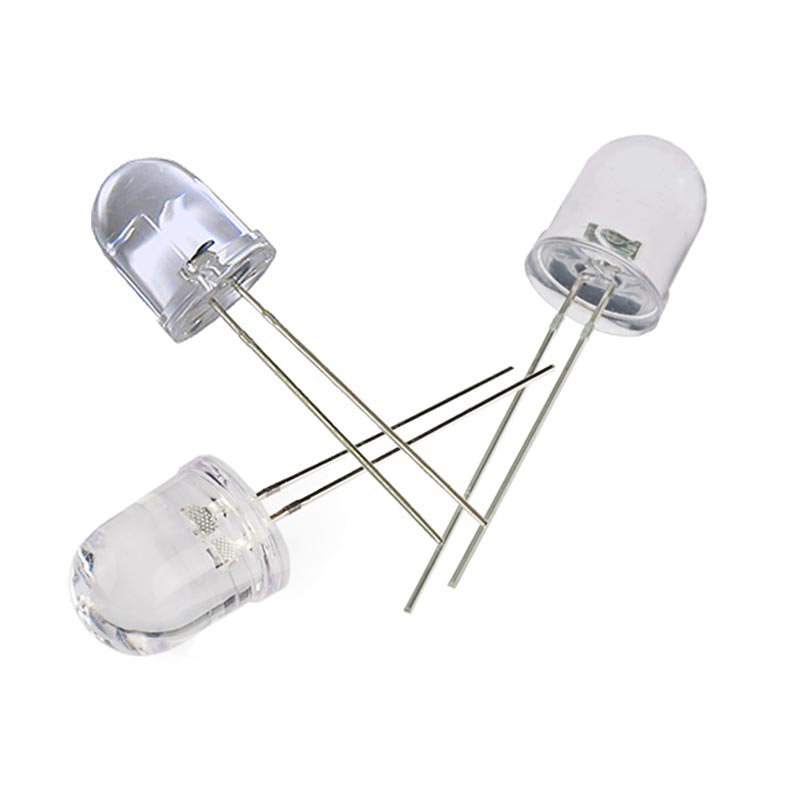
Light emitting diodes are great for blinking and flashing in various projects, but they will burn out very quickly if they receive too much power or current. Like other diodes, electrical energy will only flow through them in one direction, so it's important to have power connected to the positive (anode) leg, which is usually longer. Read all about LEDs here. The four-legged LED is a multicolour RGB LED.

There are two types of Servo motors: continuous rotation and positional rotation. Regardless of what type of servo you have, it will only respond to values between 0 and 180 from an Arduino pulse-width modulation (~) pin.
Positional rotation servo motors have a range of movement of 180º and will move to the angle it receives with little control over speed.
Conversely, continuous movement servo motors will turn continuously at full speed anticlockwise with a value of 0, and full speed clockwise with a value of 180. A value of 90, give or take, will result in no movement at all.
See the Arduino reference for the Servo library here.
components to control the flow of electricity
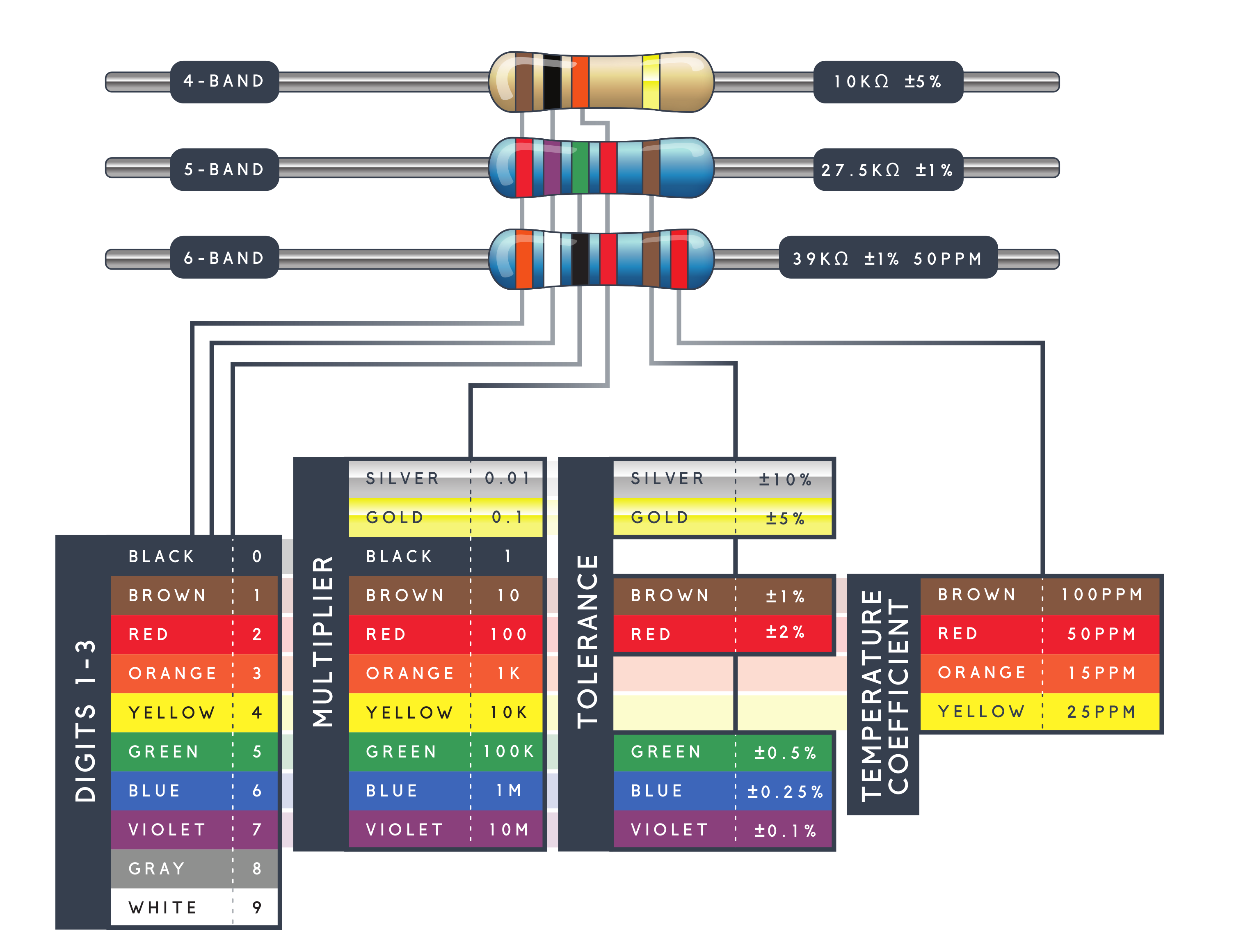
Resistors are passive components which resist or limit the flow of electrical energy. Sparkfun's in-depth walkthrough of resistors can be found here. Take particular notice of the section on decoding resistor markings and colour bands, and see this handy chart to figure out what value your resistors are. If you need more resistors, or a specific value, ask at the Hackspace in E110.

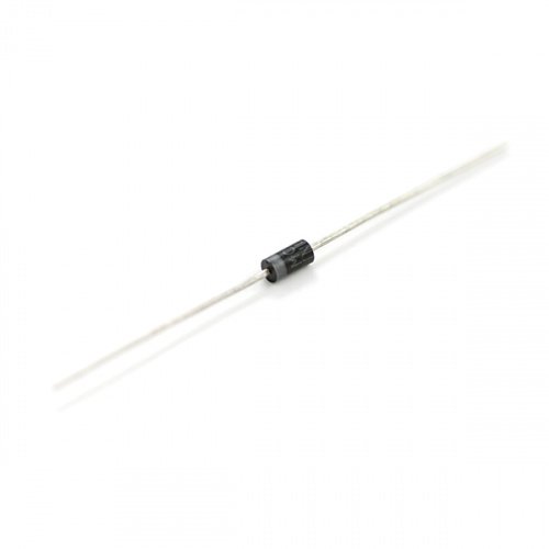
Diodes allow electrical energy to flow in only one direction. Any energy flowing in the "wrong" direction is blocked. They are often used with DC motors so as to block any kickback the motor may create. Read more here.
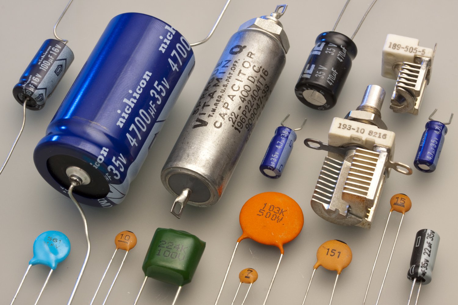
Capacitors can store electrical energy and are often used to avoid voltage spikes damaging other components, or to otherwise smooth out a signal. Read more here.
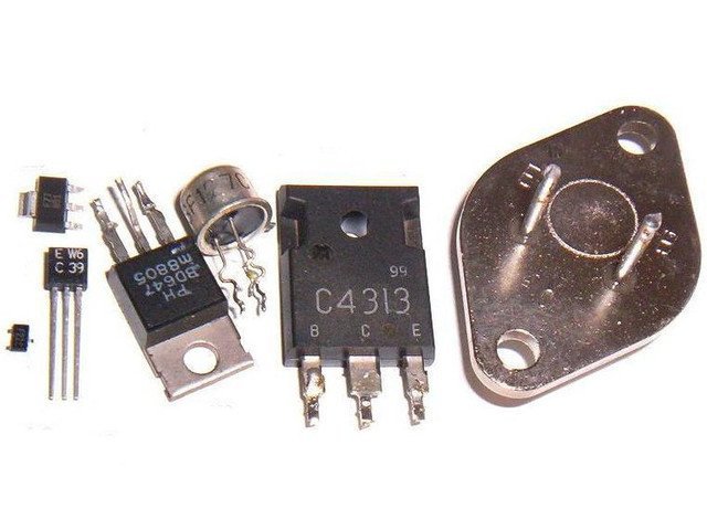
Transistors and MOSFETs are really handy when it comes to working with components that may require more power than your Arduino can provide. They can be thought of as switches or amplifiers, where you can use a digital output pin on your Arduino to connect a larger power source to components such as motors and LED strips. You can read a basic guide on the uses of transistors and MOSFETs here.