UNSW Making

Advanced CNC Milling: Feeds and Speeds (and more)

This learn module will teach more advanced CNC theory for experienced users. It is intended to be done after spending some time on the beginner mills: Tormach or Symbiosis. It is required before using the more advanced CNC mills: Datron, Haas Mini Mill or the Haas 5-axis UMC.

The process for setting feeds and speeds is:

  1. Choose your stock material.
    1. For steel you will need to know the material group, grade, % carbon or its hardness.
    2. Aluminum cuts pretty easily so there is a wider range of acceptable feeds and speeds. Generally harder aluminium cuts better.
    3. For soft material like foam and plastic feeds and speeds are important to get a good surface finish. Conventional milling is often better.
  2. Choose your machining strategy: traditional, high efficiency or high feed.
    1. This should be based on the geometry of the part and the material.
  3. Choose your tool and coating.
    1. Bigger is normally better.
    2. High feed toolpaths require tools with a lead angle or radius, not flat endmills.
    3. Certain materials will need coatings designed for temperature resistance, hardness and lubricity. But coatings reduce sharpness and are not suitable for all applications.
  4. Find the recommended surface speed and chip thickness from the tool manufacturer or a general table.
    1. The ideal surface speed depends on the material and tool coating, but isn't really affected by tool diameter.
    2. Chip thickness determines how well it cuts. Large cuts can damage a tool and small cuts can make it blunt.
  5. Choose the stepdown and stepover.
    1. These will be based on your machining strategy, the machine capability and the tool strength.
    2. If you have problems like vibration or tool breakage reducing these should be the first step.
  6. Increase your feed to compensate for chip thinning.
    1. This is most important for toolpaths with small stepovers (high efficiency machining) or toolpaths with small step-downs and a non-flat tool tip (high feed machining). This chip thinning compensation is done to prevent tools taking very thin chips (<10um) and to increase material removal.
  7. Compensate for effective feedrate at the tool outer diameter.
    1. This is most important for boring and tapping.
    2. If you have tight corners on the part you can use the "feed optimization" setting to slow the tool down in corners.
  8. Compensate for effective diameter on chamfer and ball mills.
  9. Sometimes you need to change between climb and conventional milling depending on the material.

Resources

End mills

6G tools - good for feed per tooth at different diameters, has a very low surface speed for aluminium

Fusion milling library

Hannibal Carbide Tools - good for uncoated surface speed in more materials

Do extra research for hard materials, small cutters, or unusual coatings

HSS drills

Fusion drilling library

Full retract pecking is good to clear chips

Carbide drills

HAAS

Be careful with large diameter drills if using lower torque machines

Pecking is bad (the drills are more fragile and the thru tool coolant clears the chips without needing to peck)

Shell mills

HAAS

Chip thinning

Calculator

For aluminium 5% - 20% diameter stepover

For steel 1% - 5% diameter stepover

Bigger % stepover for bigger tools

Effective feedrate

Calculator

Surface speed


Essential content

Surface speed is the velocity of the outside of the tool as it spins. We use the recommended surface speed for different materials to determine the RPM. It is related to RPM and tool diameter:

RPM = Surface speed / (Pi * Diameter)

Surface speed is important because it affects the amount of heat produced during cutting. Harder materials require slower surface speed because they produce more heat when cut.

If the surface speed is too high excessive heat will be generated. If the tool gets too hot it will reduce its hardness which can cause it to chip and break. If certain materials (plastic, aluminium...) get too hot they can melt or weld to the cutter.

High speed steel tools require low surface speed because it has low thermal stability (600C). Uncoated carbide can tolerate higher surface speeds and temperature (800C). Coatings are added to carbide to increase thermal tolerance (900C - 1100C) and decrease friction, allowing even faster surface speed. Coatings also have lots of other effects, and you need the correct coting for your material.

The benefit of high surface speed is faster cutting: if you double the RPM you can double the feed rate.

SFM (surface feet per minute) is imperial surface speed.

SMM (surface meters per minute) is metric surface speed.

SMM = SFM * 0.3048

Advanced CNC milling

Chip thinning


Essential content

What is chip thickness?

Chip thickness (also called chip load or Cl) is the thickest part of the cut, whereas feed per tooth is the distance the tool moves per cut. They are related by the chip thinning factor: Chip thickness = feed per tooth / chip thinning factor.

Chip thickness is important because it determines how the cutting edge interacts with the material. If chip thickness is too small the cutter will rub and dull. If the chip thickness is too large the cutting edge can be damaged from excessive cutting forces. Tool manufacturers will specify a ideal chip thickness.

Chip thinning diagram

Radial chip thinning

Radial chip thinning occurs whenever the stepover is less the theoretical 50% and this is the idea behind high efficiency machining. If you are using a stepover less than 50% of the tool diameter you should compensate for the chip thinning by increasing your feedrate.

Axial chip thinning

Axial chip thinning occurs on the tip of cutters with a lead angle, this is the idea behind high feed milling. Tools with a lead angle are most commonly shell mills and there are shell mills specifically designed with very small lead angles to create a large chip thinning factor.

lead angle

How to use chip thinning factor in Fusion

Use this website to calculate the chip thinning factor.

In fusion you can setup different cutting data for different stepovers. Define each set of cutting data by the width of cut (WOC) / stepover. WOC is often defined as a percentage of diameter, so for this 5mm tool a 2% WOC = 0.1mm.

For aluminium 5% - 20% diameter stepover

For steel 1% - 5% diameter stepover

Bigger % stepover for bigger tools

You can increase the 50% WOC feedrate by the chip thinning factor to get the same chip thickness. Be careful to check that the original feed per tooth is appropriate at 50% WOC, otherwise you might set the feedrate too fast.

The fusion tool library is parameterized so you can use "tool_feedCutting" and "tool_diameter" to create equations.

It is important to define the ramping feedrate, the default 333mm/min is wrong. I will often define ramping feedrate as "tool_feedCutting*0.6/chip thinning factor". It is important not to increase the ramping feed rate when you apply the chip thinning factor because there is no chip thinning during ramping. The 0.6 is included to compensate for effective feedrate.

Advanced CNC milling

Rubbing

If chip thickness is too low the tool doesn't cut, it rubs because the chip thickness is less than the radius of the cutting edge. Rubbing causes tool wear and dulling, leaves bad surface finishes, cause poor chip formation and can create dimensional inaccuracy.

New uncoated carbide tools can have cutting edge radius of about 2um, but this will increases to about 20um as the tool wears.

Coating tools will increase the edge radius and make tools duller because the coating must be applied after sharpening. Coating thickness can range from 3um to 20um.

To avoid rubbing you need to feed fast enough that the chip thickness stays significantly above the edge radius of the tool, a safe minimum is 30um chip thickness. This minimum chip thickness is harder to achieve on smaller tools.

white space Advanced CNC milling

Machining strategies: high efficiency and high feed


Essential content

Traditional milling uses a medium stepover (20-50%) and medium stepdown. It has lower material removal rates and wears tools faster than necessary by concentrating cutting forces over a small area of the endmill. It is a high torque, low feed process.

High efficiency and high feed milling are two alternative strategies that can increase the material removal rate and tool life. Confusingly, both high efficiency and high feed use high feed rates.

Traditional High efficiency High feed
Stepover Medium stepover (20-50%) Small stepover (1-10%) Large stepover (60-100%)
Stepdown Medium stepdown Large stepdown Small stepdown
Feed rate Low feed High feed High feed
Chip thinning None Radial chip thinning Axial chip thinning
Tool type Endmills, insert mills Endmills High feed insert mills, high feed endmills, endmills with corner radius
Intended toolpath Adaptive or Pocket roughing Adaptive roughing Pocket roughing, ramping contour

High efficiency milling

High efficiency milling uses a small stepover (1-10%) and large stepdown and is used with endmills. It takes advantage of radial chip thinning to feed faster. The large stepdown distributes the cutting forces over the entire length of the cutting edges, which reduces temperature, tool wear and vibration. The small stepover reduces the torque on the spindle, which is why it is ideal for the Datron.

If you are not sure what stepover will work, start small. Stepovers as small as 1% can be used if you do the math to avoid rubbing. Small stepovers will reduce tool load and deflection. Then increase the stepover until the spindle load becomes too high or vibration sounds too loud.

Fusion uses adaptive clearing for high efficiency toolpaths. Unfortunately fusion calculates the toolpath based on stepover rather than tool engagement angle, so there can be large spikes in cutting force at internal corners. To reduce these spikes, make corner radii > tool diameter as much as possible, and you can use "feed optimization" setting to slow down the feedrate in corners. See the effective feedrate section lower down to work out how much to reduce the feedrate by.

white space Traditional milling versus High efficiency milling
white space
white space

High feed milling

High feed milling uses a large stepover (60-90%) and small stepdown. It takes advantage of axial chip thinning to feed faster. It can be used with shell mills that have a lead angle, high feed endmills or tools with a corner radius like bull and ball nose endmills.

High feed milling is most useful in steel because it reduces tool deflection by directing the cutting forces mostly vertically up the spindle. The shell mills used are also larger diameter and therefore more rigid. The inserts for shell mills can be more easily and cheaply replaces than endmills when they wear out.

white space

Effective feedrate compensation


Essential content

Effective feedrate calculator

The actual feedrate of the tool is the programmed feedrate (e.g. F1000) and it is the feedrate at the center of the tool. Effective feedrate is the feedrate at the outside diameter of the tool. Effective feedrate determines the chip thickness and therefore the cutting force.

For linear paths actual and effective feedrate are the same, so the tool cuts as expected. However whenever the tool cuts a circular path (bores, threading and fillets) the outside of the tool travels a different distance to the center of the tool so there is a difference between the actual and effective feedrate.

When doing internal cutting, the outside of the tool travels faster than the center of the tool. This means the tool has a higher chip thickness than programed, which can break or wear tools and leave bad finishes. To fix this, the actual feedrate can be slowed down to make the effective feedrate match the desired feedrate. This is especially important when the size of the tool is close to the size of the hole, like in threading or boring.

When doing external cutting the outside of the tool travels slower than the center of the tool. This is less likely to be a problem, but it can cause rubbing if the desired feedrate is already close to rubbing.

There are three important situations that need effective feedrate compensation: ramping, circular toolpaths and tight corners.

white space Advanced CNC milling white space Advanced CNC milling

Tight corners

Use Feed Optimization

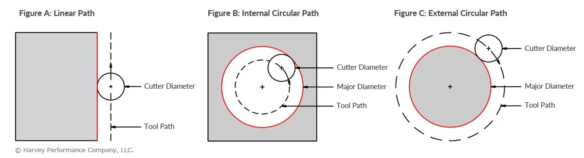
This is the most common and important application of effective feedrate compensation.

When cutting sharp or small radii corners (adaptive, 2D contour) the toolpath will have a sharp corner or a small radii corner. When the tool tries to cut into the corner it will experience a spike in radial engagement (what angle of the tool is cutting). This unexpected increase in cutting force can cause vibration and break the tool.

The best solution is to increase the fillet radii as much as possible. Try not to design parts where the fillet radii matches the tool radius. However, even with bigger fillets the tool engagement still spikes in corners.

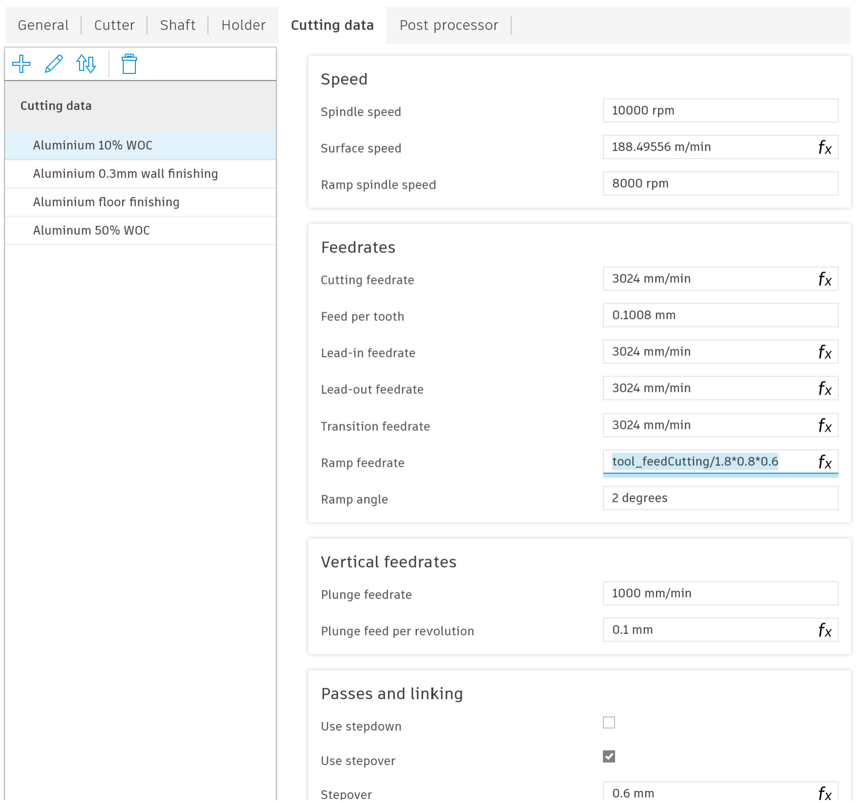
To reduce the cutting force in corners Fusion has a setting in most toolpaths called feed optimization, which reduces the feedrate in corners. Feed optimization will help you avoid damaging tools and get better corner surface finishes. Best of all, if you save some smart user default settings feed optimization will protect you automatically most of the time. Copy and save as user default the following formulas into your feed optimization settings for each toolpath (most important are adaptive, pocket, 2D contour, chamfer)

Reduced Feed Radius =

max(tool_diameter * 0.05; minimumCuttingRadius * 1.05)

If you are cutting tight fillets work out the minimum radius the toolpath will turn and set Minimum Cutting Radius to that value. This will automatically update Reduced Feed Radius and Reduced Feedrate.

Reduced Feed Distance depends on how much stock is in the corner. You should simulate the toolpath and watch from above to make sure it slows down before engagement increases.

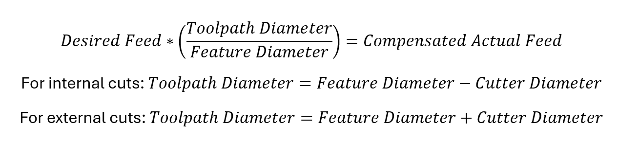
Reduced Feedrate = tool_feedCutting *(reducedFeedRadius*2)/(tool_diameter+reducedFeedRadius*2)

The formula for Reduced Feedrate is multiplying the cutting feedrate by the effective feedrate factor.

white space feed optimisation

Feed optimization shows as yellow in your toolpath

white space Screenshot 2026-03-26 081746

Save settings as user defaults

To get feed optimization to turn on by default is weird because there is no obvious button to save as user default. You have to right click on the toolpath and enter compare and edit mode. Then find feed optimization, set it to Yes and right click to save as user default.

Screenshot 2026-03-26 083801 white space Screenshot 2026-03-26 084009

Ramping

Set the Ramp feedrate

During many toolpaths such as adaptive and pocket roughing the tool will helical ramp into pockets. You should set the ramp feedrate every time you create a new tool (do not leave the default 333, it is dangerous).

As an extra note, ramping is much more intense on the corners of the tool because it it cutting on the side and the bottom at the same time. To reduce the intensity it is recommended to reduce the RPM to 70% - 90% of normal (in the example I have a ramp spindle speed of 8000 RPM, 80% of spindle speed). This is more important in harder materials.

There are three factors that determine your ramp feed from you cutting feedrate: chip thinning factor, RPM factor and effective feedrate factor. If you have applied chip thinning to your cutting feedrate you need to divide by the chip thinning factor because the tool is fully engaged during ramping and there is no chip thinning. If you are running a lower ramp spindle speed you need to apply the same reduction to the ramp feedrate to keep the feed per tooth the same. Finally during ramping the tool typically cuts a circle slightly smaller than 2*tool diameter, which gives a effective feedrate factor of 0.5. I usually use a effective feedrate factor between 0.6-0.8 instead of 0.5 to reduce rubbing.

If you are doing contour ramping rather than circular ramping, the effective feedrate factor doesn't apply.

In the example image I have use a ramp feedrate of tool_feedCutting/1.8*0.8*0.6. The /1.8 is to undo the 10% WOC chip thinning factor. The *0.8 is because I am using 80% ramp spindle speed. The *0.6 is the effective feedrate compensation.

ramping feedrate

Threading

Create internal and external thread cutting profiles

It is very important to compensate for effective feedrate when threading because the tool moves in a very small diameter spiral.

Choose an appropriate feed per tooth and then multiply by the effective feedrate factor.

Screenshot 2026-03-25 093120 Screenshot 2026-03-25 093532

Boring

Manually adjust feedrate

Boring is very similar to ramping, except that it uses the cutting feedrate instead of the ramp feedrate. To set the correct feedrate you can multiple the cutting feedrate by the effective feedrate factor manually in the toolpath.

Screenshot 2026-03-25 112850

Effective diameter compensation


Expert content

When using tools that don't contact on the outermost diameter you might need to compensate for their effective diameter. This is most common in chamfer mills and ball nose endmills. There are two things you can compensate for:

  1. Increase the RPM so that the surface speed at the effective diameter is correct.
  2. Decrease the chip thickness. At smaller diameters the flutes are smaller and cannot take large chip thicknesses.

Climb VS Conventional


Essential content

Summery: Climb is better on CNC machines for hard materials (metal, most wood, hard plastics). Conventional is better on manual machines and for soft materials (foam, soft wood, soft plastics).

Upmilling-vs.-Conventional-Milling
Climb Conventional
Rubbing Starts cutting at the thickest part of the chip, so no rubbing issues. Starts cutting at the thinnest part of the chip so will rub until the chip is thick enough. This reduces tool life in metals.
Chip evacuation direction Evacuates chips behind the cutter so less chance of recutting chips. Evacuates chips in front of the cutter so can cause chip recutting.
Surface finish Leaves better surface finish on metal, wood and hard plastics. Leaves better surface finish on foam and soft plastics.
Backlash Causes backlash problems on manual machines, but not a problem for CNC machines. No backlash problems on manual mills.