UNSW Making

Basic CNC Milling: Tooling

CNC Milling Basics Module 2: A Closer Look at End Mills and Beyond

2.1. Endmill vs. Drill bit:

The end mill is the workhorse of CNC machining. Despite its resemblance to a common household drill bit, and the frequent confusion between the two, they are distinct tools designed for different machining functions.

Drill bits are crafted for plunging vertically into materials to ‘drill’ cylindrical holes, while end mills are designed for lateral cutting.

End mills feature sharp spiralled cutting edges named teeth (or tooth), which efficiently cut as the endmill gradually moves sideways into the material.

CNC Endmills no title-04.png

2.2. Endmill Shape:

Many different types of end mills are used to achieve different geometry. Within this basics badge we will be covering Flat end mills (FEM) and Chamfer mills as a stepping stone to more complicated designs. These two end mills are the most common tools used when CNC machining and will service the majority of your basic parts. More intricate and complicated end mill types are covered in CNC Intermediate.

CNC Basics - FEM and Chamfer _1

Flat End Mill (FEM):

These bits are commonly used for removing material and finishing horizontal and vertical surfaces. FEMs shine in their ability to remove lots of material very efficiently, known as roughing.

As you will see in this badge, FEM can also be used to bore holes, create pockets and contour profiles. We will cover some of the key geometric limitations and anatomy of the FEM in the next section.

removing material FEM
flat_end

Chamfer Mill:

Chamfer end mills feature a V shaped tip and are commonly available in 90- and 60-degree angles. They are used to create chamfers, break sharp edges & engrave fine details.

Chamfers are typically used to improve the assembly of mating features, to improve safe handling and for aesthetics.

chamfer example 4
Chamfering 2

2.3. FEM Anatomy:

It’s important to understand the anatomy and lifecycle of an endmill to determine its functions and limitations. For this badge the tooth, flute, Flute length, diameter and stick-out length are the most critical components you need to know to start modelling and cutting.

fem anatmoty 2

Tooth & Flute:

An endmill tooth is the cutting edge of the mill. The number of edges (teeth) depend on the number of flutes. Flutes are the deep, spiralled grooves facilitate chip formation and evacuation, assisting in the cutting of the material. The number of flutes influences the chip size and surface finish (as expanded upon in CNC Intermediate, it also dictates how fast and hard to push the end mill through the material).

flutes

Flute Length & Diameter:

Flute length dictates the maximum cutting length of the endmill.

The diameter determines the maximum cutting width. Using the full diamater of an endmill is known as slotting, and as we will discuss should be used in limited circumstances.

The smaller the diameter, the smaller the features you can create, however the trade-off is reduced stiffness. A smaller diameter tool can break more easily under realtive loads.

Stick-out length

Stick out refers to the length of the tool protruding from the collet or tool holder. This distance dictates the maximum reachable depth of features that can be machined, but it also directly affects tool stiffness.

We can model the cutting tool as a simple cantilever beam fixed at the tool holder with a load applied to the end. Because maximum deflection increases with the cube of length (L), even small increases in sickout significantly reduces tool rigidity, as seen in the ruler demonstration shown. When setting our tools we aim to improve rigidity by reducing tool stickout and using thicker tools when allowable.

PET_Ruler_Vibrations (2)

Deflection should be minimised as much as possible to reduce errors in machined surfaces, dimensional inaccuracy, vibration (chatter), poor surface finish and tool wear.

deflection_thick

Life Cycle and Tool wear.

Just like a kitchen knife that has been used for too long, and endmill loses its effectiveness to cut the more it's used. We call this tool wear, and it’s important as a machinist to manage this wear to prolong the useable life cycle of an endmill and to successfully machine our designs.

We manage tool wear by selecting the correct tools for the job and optimising how we cut into the material called, feeds and speeds (coming in the next section). However, even with the most optimal strategy tools eventually degrade over time, it’s likely that if the quality of your parts decline it’s time to check the bit for wear.

In summary, endmills are a consumable item, so don’t worry if they need replacing after prolonged use. Come ask a staff member and they will help you discern if your tool should be replaced. Below is a few examples of tool wear, inlcuding tooth chipping and edge dulling.

ToolWear

2.4. Feeds n’ Speeds & Bite size.

Feed vs Speed (2)

What are Feeds and Speeds?

Feeds and speeds are critical parameters in machining. Feed rate, measured in mm/min (feet/min for you imperial loyalists), defines how fast the tool advances through the material.

Spindle speed, measured in revolutions per minute (RPM), defines how fast the tool rotates. Surface Speed (mm/min), defines how fast the the cutting edge travels relative to the workpiece.

These parameters depend on several factors including the workpiece and tool materials, tool geometry and the CNC machine's specifications.

To begin your understanding of feeds and speeds, the basic Fusion 360 "recipe" is outlined in the diagram below. This topic is covered in more detail in CNC Milling Intermediate, including the underlying formulas, calculations and further considerations. There, you will determine your own feeds and speeds for different tools and operations. For now let's start our understanding

speeds and feeds basic recipe

Surface Speed [mm/min]: The linear velocity at the cutting edge. How fast the edge of the tooth is moving.

Material classes are machined at varying surface speeds due to differences in hardness and heat generation. Steels are typically machined slower than aluminium because they generate more heat during cutting due to their toughness and hardness.

Milling tools are commonly made from tungsten carbide due to its high stiffness and hardness. Coatings are often added to improve performance in harder materials, which can also change the recommended surface speed.

A tool manufacturer's look-up table (such as this one), will provide the recommended surface speed accounting for these two factors, and is our first input to the recipe above.

With the tool diameter known (the second input to the first row), we can calculate the required RPM to acheive the specified surface speed. Now to the second row, the last remaining input is the Feed per Tooth.

surface speed 4

Feed per tooth (FPT) [mm]: The distance the cutter moves during one tooth engagement, effectively the thickness of material removed by each cutting edge, as seen to the right.

If FPT is too low the tool can rub instead of cut, producing excess heat. If too high it can overload the tool and machine. The FPT ideal range is dependent on a multitude of factors, however, tool manufacturers rigoursly test their tools to define an optimal range and is often (but not always) provided often we have to research based on other suppliers.

FPT

And that's it for now. With FPT and RPM (the one we previously calculated) we can finally determine the feed rate!

What is DOC and WOC?

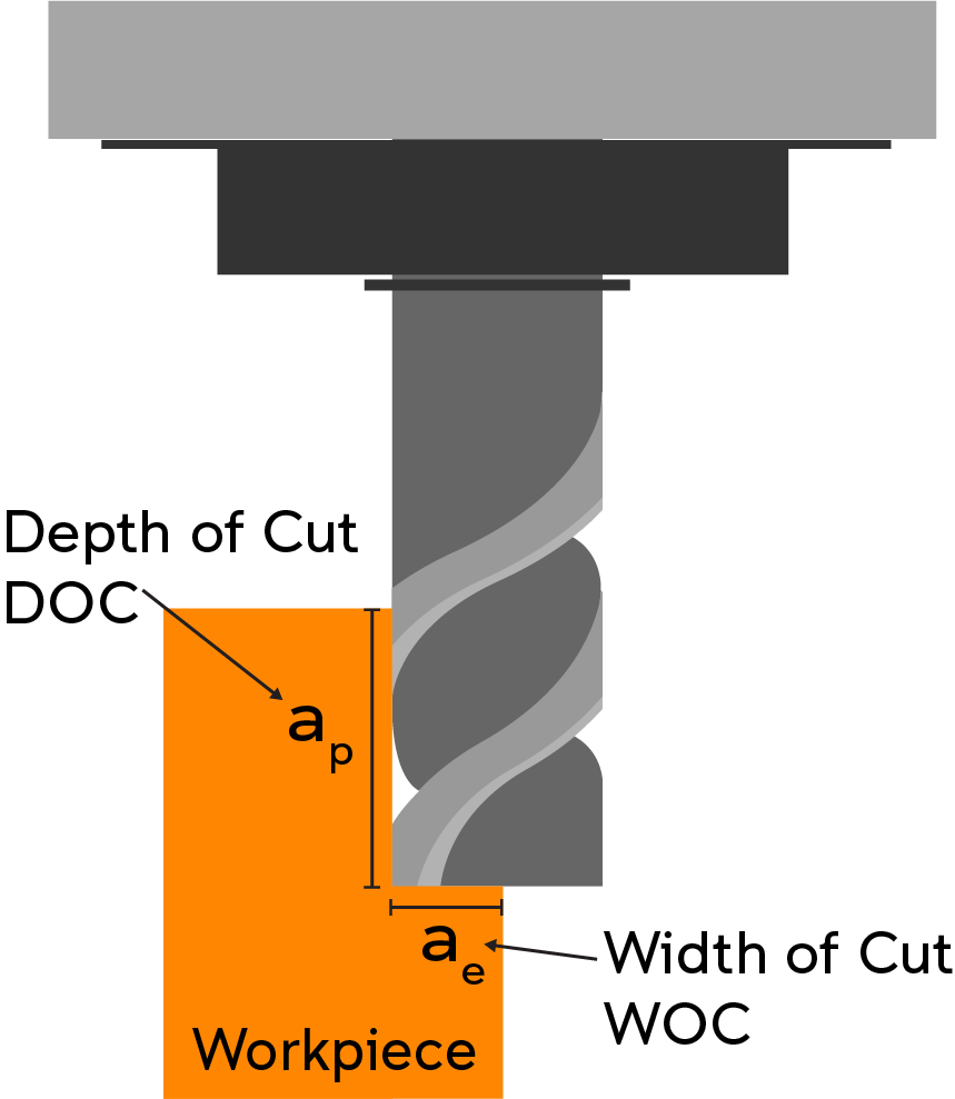
Depth of cut (DOC) and width of cut (WOC) describe how much of the tool is engaged in the material. Together they define how large of a “bite” is being taken, this influences our cutting force, material removal rate, tool wear, dimensional accuracy, feeds and speeds, and workpiece finish.

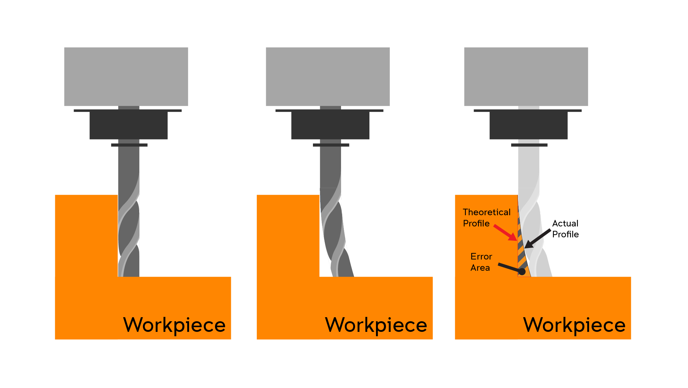
DOC is the depth the tool penetrates the material along its axis (a_p on the right). The theoretical maximum DOC is the tool’s flute length, but can depend on the depth of desired features, strategy of cutting and the width of cut.

WOC is the width of material engaged by the cutting tool across its diameter, (a_e on the right). This radial engagement introduces side load onto the tool, exciting deflection and bending. The theoretical maximum WOC is the tool diameter.

DOC and WOC share a tug-of-war relationship, increasing one should reduce the other. If both are maximised, force rises rapidly, increasing deflection, tool stress and the risk of tool breakage. As expanded upon in CNC intermediate, good practise maximises an endmill's DOC and mitigates the WOC accordingly for optimised chip formation.

DOC and WOC (2)

Due to the power limitations of the desktop CNCs, the traditional speeds and feeds calculations are not as directly applicable, and it can struggle to remove material at a high rate.

For CNC Milling Basics a library of optimised Feeds and Speeds and bite size for each tool is provided for you in a future module. This library will demystify one of the most difficult aspects of beginner CNC machinist and start you on the way to manufacturing basics parts.

2.5. Considerations to design & limitations of tools:


Here's a few useful tips

Due to the geometry of the tool and limitations of accessibility of a 3-4 axis CNC machine style, some features and geometry cannot be manufactured. It’s important to inspect CAD designs for these features and here are a few to look out for.

Internal Radii

As an endmill has a circular cross-section, they inevitably leave fillets equal to the radius of the tool on the internal corners of designs. Achieving sharp internal corners where two faces meet with a round tool is impossible! This detail becomes crucial when attempting to create joinery or complementary parts that fit together seamlessly. An internal corner fillet must be greater than the radius of the tool being cut in order to achieve the desired design.

Artboard 11

Dogbones are a solution to internal radii, as seen in the figure above. By adding a subtractive fillet to the internal corner, a square cornered part can be assembly with mating faces.

aCCESSIBILITY (2)

Overhangs/Accessibility.

Accessibility is a major consideration when using 3-4 axis machines, imagine taking a bird’s eye view of your part, this is the perspective of the tool in machining. Any features that cannot be seen typically cannot be machined (a few advanced exceptions exist). Features under overhangs or on faces not accessibly by the tool obviously cannot be machined.

Reach

The tool cannot cut longer than it can physically reach. Take a bore (a hole) feature as an example as seen in figure x. This reach is dictated by the tool stick out, flute length and tool geometry below the holder.

Additional design advice:

Knowing how to design for CNC milling is the first important step in your journey as a CNC machinist. Here is a useful video covering what we've learnt and some additional advice.

Categories: Manufacturing
Tags: CNC