UNSW Making

Basic CNC Milling: Fusion 360 CAM

CNC Milling Basics Module 3: Learning CAM - Starting at basics

CAM is the mode by which we create G-code to communicate to the CNC. Mastering CAM is a challenging aspect of learning CNC milling, but this module will guide you through the basics for you to start making simple parts, a stepping stone to achieve more complex and accurate designs in the future.

In this module we will teach how to use Fusion 360’s CAM package, due to its availability and accessibility. There are other CAM softwares used in industry include MaterCAM, Solidworks CAM, Onshape CAM Studio etc, but require additionnal licenses to use, and can have a steep learning curve.

In essence, to CNC machine a design we adhere to the following CAM workflow:

CAM_workflow_diagram

Fusion 360 Workflow Demonstration (Essential):


Makera Desktop CNCs: Carvera, Carvera Air & Z1

Before we start, make sure you have Fusion 360 downloaded and installed (we recommened to to create an autodesk account with your university email to get the education license). Next, download and import the tool libraries for the Carvera Desktop CNC mill. The Fusion 360 website offers instructions on how to import an existing tool libraries.

The Carvera, Carvera Air and Z1 are available at the James Kirby Engineering Makerspace and within the UNSW Making network.

IMPORTANT: The laser cutter modules have been disabled on all Desktop CNC's within the network.

desktops in the network

3.1. Have a 3D Model:


Start with your CAD model:

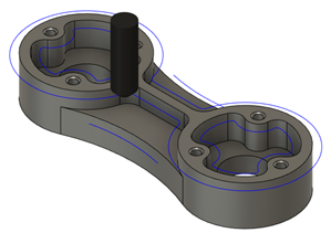
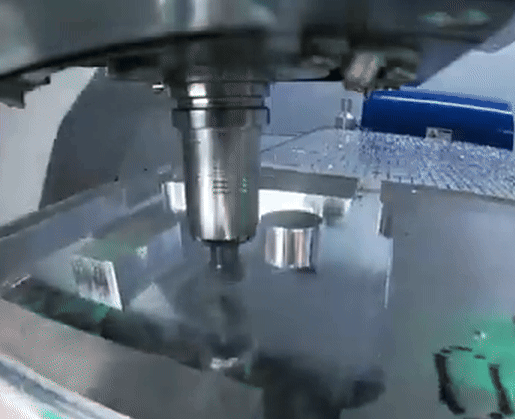
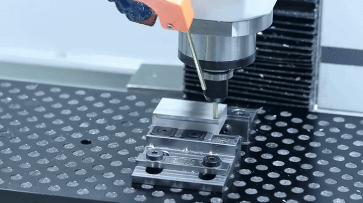
To begin you must have a CAD model of your desired design. It can be a native fusion file (.f3d), but you can also import files from other CAD packages such as SolidWorks or OnShape via STEP format. In general,.Stl files (like those used for 3D printing) need prior processing before we can CAM them easily (This link shows a method). If you need help creating a compatible file, come speak with the makerspace staff.

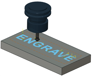
2D vector files such as .dxf and .svg can be imported for engraving faces or surfaces. But be warned some complex designs are difficult to achieve.


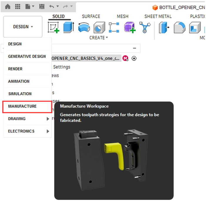
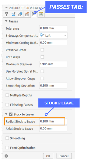
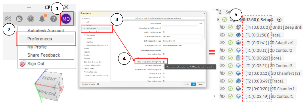
To start setting up your CAM, move from the DESIGN tab to the MANUFACTURE tab at the top left window, as seen to the right. We can move back to the DESIGN tab to make edits to our design or make sketches to reference at any time.

manu_tab_enhanced2

3.2. Setup:


Create your Stock and WCS

The setup menu is the foundation of your CAM. It defines the following:

  • The model you are machining (useful to define in assemblies of multiple components),
  • Your Work Coordinate System,
  • The volume of your stock, and
  • Any components you would like to avoid (we can model our fixtures and actively avoid them)

Click on New Setup icon and see the setup tab open.

setup_icon_f360

We need to be mindfull that the WCS must live where it is accessible by the CNC head. For the majority of simple parts selecting this location as a corner at the top of our stock is perfect. Select your box point

stock icon

To define your stock volume, select the stock menu tab. stick with a fixed sized volume and specify your starting stock dimensions.

The setup folder will house all our different operations at the specified WCS orientation. If I want to mill my design from a new direction or reach features that are inaccessible in this WCS, I’ll have to specify a new setup with a different WCS.

Setup Menu

3.3. Milling Operations:


Which operations should I choose to make my designs?

We can broadly catergorise our operations for removing material into two methods, Roughing and Finishing.

Roughing aims to remove material quickly and efficiently, establishing the 'rough' profile we desire, with minimal 'Stock to leave'.

Finishing involves one or more final passes to remove the small remaining stock, achieving the required dimensional accuracy and surface finish. But there are some limitations to consider.

In our our CAM majority of operations are versitile, they can be used to both rough and finish parts. Some roughing strategies allow for an additional 'Finishing pass" at a smaller bite size, whilst some do not. Below outlines the basic 2D operations available to you, their features and when to use them. As you gain experience the choice between operations their 3D counterparts and others will become clearer.

Operation Menu:

Once an operation is selected the six properties shown below will appear to the right of our window. These six tabs are always the same or have the same functions no matter the chosen operation, making it easy to remember the workflow. For this module we'll concentrate on the five most important:

fusionCAM_operation properties

Facing:

Facing_f360_icon

The Face toolpath is often the first operation performed on raw stock material to prepare it for further machining. Typically, the depth of material to be removed is the distance between the top of the stock and the top of the model. This toolpath is used to ensure flatness on a surface so it can sit flat on a vise for accurate machining. It can also be used for clearing flat areas in general. the WOC is around 70% of the width of the tool, so consecutive passes overlap (defined as the Stepover within the passes tab).

Typically in our larger CNCs, a large diameter face or shell mill (as seen to the right) is used to take cuts with a high DOC and WOC. However, for our less powerful desktop CNCs, a much shallower DOC of 0.1 mm using our FEM is required. This is changed within the passes tab by enabling multiple depths and specifying the Maximum Stepdown value, as seen in to the right. You can also add a finishing step within the Multiple Depths tab.

Operation type: ROUGHING and FINISHING

Stock to Leave: ✅

Multiple Depths: ✅

Finishing Pass: ✅

2d-facing_f360


facing_gif


Watch this in full screen!

facing_bite(2)

2D Adaptive Clearing:

2d adaptiove_f360 icon

2D Adaptive Clearing is a roughing toolpath that avoids abrupt direction changes. You can clear a cavity, open pocket, or the area around a boss by selecting edges, sketches, or solid faces as the machining area on the same plane. This toolpath maintains a constant engagement between the tool and its surrounding material, a much healthier strategy for managing tool wear.

The Optimal Load (WOC) and Maximum Roughing Stepdown (DOC) is specified under the Passes tab, as seen to the right . As discussed, our smaller CNCs are not very powerful, meaning a shallow bite is needed to not overload the spindle. The downloaded tool paths have these parameters preset.

A recommended radial and axial stock to leave of 0.1-0.05 mm for vertical walls and horizontal floors is recommended.

Operation type: ROUGHING

Stock to Leave: ✅

Multiple Depths: ✅

Finishing Pass: ⛔

2d-adaptive-lp-read-toolpath-image_f4360


adaptive_gid(2)


Watch this in full screen!

ADAVPTIVE_PASSES_2

Boring:

bore_f360_icon

Bore is used for helical milling into holes or bosses that have straight or tapered walls. This technique is essential for machining large or non-standard hole sizes, such as 8.45 mm, where specific drill sizes are unavailable. You can use the bore toothpath to refine and enlarge holes initially made by drilling or other methods, but it is not a requirement for the router style desktop CNCs used in this badge.

Select any internal or external faces to create the toolpath. The heights and depths are automatically derived from the selected face. We can define multiple passes for roughing, or a finishing step. A hole must be larger than the tool diameter to helically bore.

For holes larger than 170% of the tool diameter use Multiple Passes. When dealing with holes significantly larger than the tool diameter, for example, a tool 200% larger than the tool diameter, an adaptive roughing operation can be used. On our desktop CNCs, we recommend not boring holes larger than 70% of the flute length in one pass, otherwise issues with chip evacuation, cooling and spindle power arise.

Operation types: ROUGHING and FINISHING

Stock to Leave: ✅

Multiple Passes [Radial direction]:✅

Finishing Passes: ✅

2d-bore_f360


bore example


Watch this in full screen! [IMPERIAL UNITS]

boring_hole_bottom

When boring a through hole (a hole passing completely through a part), we must ensure the tool breaks through the part. Set the Bottom Height offset to be slightly under the hole botttom (-0.1 to -0.2mm) in the Heights tab, as seen above.

2D Chamfer:

2d chamfer f360 icon

The 2D Chamfer toolpath is used to create a beveled edge on a part. Select edges or sketches to drive the toolpath. A chamfer mill is required to create a smooth chamfer. Since CNC machining can create sharp edges, we advise you edge break with small chamfer width of 0.1-0.2 mm should geometry allow it.

Within the Passes tab we can moderate the chamfer width, the tip offset of the tool and the minimum clearance as seen to the right. These paramters change the geometry of the chamfer and how our tool interacts with the selected edge. We will demonstrate what these change within the Carvera badge activity.

Operation type: FINISHING

Stock to Leave: ⛔

Multiple Depths: ⛔

Finishing Passes: ⛔

2d-chamfer_f360


Chamfer_gif(2)


Watch this in full screen!
[IMPERIAL UNITS]

chmafer_f360_settings

2D Pocket:

2dpcoket_f360_icon

The 2D Pocket toolpath is similar to 2D Adaptive, but there are two distinct differences. Firstly, 2D Pocket is contrained within the selection boundary, and secondly, the path does not optimise for tool loading. While it can be for roughing, if the bite size is not carefully considered it can produce hazardous toolpaths.

For this basics badge we'll use 2D pocket to finish the horizontal floors of our designs ONLY, while leaving 2D Adaptive for roughing.

The machining area can be selected from edges, sketches, or a solid face. You can select multiple pockets, at different heights, to machine during a single operation.

Importantly, as we are finishing the floors you must allow RADIAL stock to leave on the walls of your pocket. We will finish those walls later with another toolpath.

Operation type: FINISHING

Stock to Leave: ✅

Multiple Depths: ✅

Finishing Passes: ✅

2d Pocket fusion image


DATRON_CNC_Mill_Pocketing5


Watch this in full screen!

POCKET_PASSES_1

Trace & Engrave:

icon_64x64 (1)

The Engrave toolpath is commonly used to machine text and imported art work. The toolpath requires tools that have pointed tips (chamfer or engraving tools). The tip of the tool is used to create sharp edges on the pocket's corners. For engraving text, the Engrave toolpath physically outlines the selected font of your design, this can often lead to unlegible writing if the DOC is not carefully considered.

An alternative option to achieve easily legible text is tracing a vector font (.shx suffix) with the Trace toolpath. This follows the exact internal path leading to clear design, as is advised for beginners. We can moderate the depth of the engrave via the Axial offset, within the Tp

Trace = Vector font - moderate dept

Engrave = Regular font (engraves outline)

There are other toolspaths (like engrave) thatw e will cover in intermediate.

Operation Type: FINISHING

Stock to Leave: ✅

Multiple Depths: ✅

Finishing passes: N/A (repeat passes)

engrave_f360


Watch this in full screen! [IMPERIAL UNITS]

engrave_gif

2D Contour:

2d Contour f360 icon

2D Contour creates a toolpath based on a contour selection, which is an outline of a part or feature. 2D Contour is commonly used as a finishing toolpath. You can use multiple depths to avoid cutting with the full depth of the cutter.

The outline of a design can be profiled using a constant ramp cut, this is very useful for sheet material or thin parts as a last step to obtain your design. An example is seen to the far right. However, if we ramp to the bottom of our material our part will fly away! We solve this by leaving tabs connecting our design to the stock to help hold it place (this is covered in workholding in the next module).

Operation Type: FINISHING (walls)

Stock to Leave: ✅

Multiple Depths: ✅

Finishing passes: ✅

2d-contour_f360


2d contour_gif


Watch this in full screen!

rAMP_LINKING_TAB rAMP_EXAMPLE (ANNOTATED) Milling-Machinist-Rule_gif

Stock to leave: (Setting)

For all roughing operations, the Stock to Leave (STL) feature preserves a layer of material for more precise and improved finishing in subsequent passes.

The Axial setting specifies the thickness of material left along the Z-axis (vertical walls), while the Radial setting applies to the XY-plane (horizontal surfaces).

For an optimal surface finish on the Desktop CNCs, it is recommended to leave a material thickness of 0.1- 0.05 mm in roughing, and finish with a finishing step or seperate finishing tool path (2D contour or 2D pocket). For the larger CNCs a STL of 0.2-0.5mm in roughing is advised.

STL can be toggled under the Passes tab of the roughing operations listed above.

StockToLeave3

Limitations and Strategies for tool operations.

Maximum End Mill Engagement When Roughing

If an end mill is inserted into the material too abruptly, it faces an excessive load that may cause it to break. Conversely, cutting too slowly can lead to grinding, friction, excessive heat, and accelerated wear of the tool. The load on the tool should ideally be constant and adjusted with care.

To prevent tool breakage during roughing, it is essential to use slow, gradual passes that step down and move radially to cut the material. Mastering the proper configuration of end-mill engagement for clearing requires practice and experience. Sticking to the provided tool library parameters is recommended as a conservative starting point.

Maximising Axial/Radial Engagement when Finishing

The quality and precision of a part are significantly influenced by how the tool interacts with the surface during finishing. Finishing toolpaths are typically performed with with much lower tool loads to reduce tool deflection and vibration.

To achieve the best vertical finishes, utilize the maximum length of the flute available without engaging the end of the bit to increase tool stiffness.

For optimal finishing of horizontal surfaces, maximise engagement with the outer edges of the tool end, while avoiding the tool centre. Surface speed approaches zero at the centre of the cutter and so cuts poorly.

cnc_crash_5


crashing_CNC_3

3.4. Simulate & Inspect:


Check your CAM is doing what's intended

To ensure we have no unexpected collisions and your CAM is doing whats expected it’s critical you inspect the timing of your operations and simulate.

Operation Timing:

To turn on your operation timing (how long your setup and operations will take), head to your Preferences > Manufacture and toggle ‘show operations machining time’, as seen in the figure below. This is a great way to determine which operations are taking the longest for better optimisation, and to catch any easy mistakes. This is a default setting for all your future CAM programs.

turn on machine operation timing

Simulate:

simulate f360 icon

When simulating your operation, we can inspect if the cutting tool will behave as intended, and if our desired design has been machined to our theoretical desired dimension. To better discern this toggle your stock colourisation to Comparison Mode, this will show:

Blue = positive material (unmachined material),

Green = to-tolerance material (final dimensions) and

Red = negative material (over-machined material).

A finished design should be all green😊.

Simulation also throws errors if the tool experience plunges or other issues, these are indications that you should change your approach, or a mistake has been made in your operations.

You must also consider your fixturing too. Ask yourself will my operation avoid my chosen fixturing strategy? Will my operations machine into the bed or collide with the vice jaws? All important considerations when simulating.

Once it is fully simulated without concern, then you’re ready to post-process your designs.

comparison mode

3.5. Post-Process


Convert your CAM to the language the CNC speaks

post-process f360 icon

After completing our setup, operations and simulating our toolpaths we are ready for the final step, post-processing. This converts your CAM into G-code, which is saved as an .nc file extension. To post-process, select the icon seen to the right. A menu will appear with two tabs and three key actions:

Settings Tab:

  • Post – if G-code is the language of the CNC, the post is the ‘dialect’. Different vendors (Carvera, tormach, Hass, FANUC) have different conventions for interpreting your G-code. Selecting the correct post file is critical as different machines can’t read post from different vendors.
  • File name – the name of your file (some CNCs only take numerical names)
  • Output folder – Where will the post be saved to. We recommend you keep a folder for all your Carvera posts on your personal device.

For Makera’s Carvera model of CNC the follow post-processoris needed, you can save this top your local post library. (click on the link below)

Makera Carvera Post-Processor: :Makera Carvera/ Carvera

To add a new post to your local library, follow these instructions.

In CNC intermediate we will look over reading some of the critical commands of the G-code and what they instruct, so stay tuned.

posting_annotated_settings&ops (2)

Operations Tab:

The Operations tab tells the post-processor which operations to include in the post. We can select and deselect to post individual sections or all operations together.

Additional Toothpaths:


Non-essential toolpaths but very useful to know

Drilling:

drill_f360_icon

The Drill toolpath is a common machining process for creating holes in the work piece. It is most suitable for smaller, standard-sized holes where high precision and smooth surface finishes are not critical, making it ideal for rough hole creation. When drilling holes, it is advisable to perform spot drilling first. This enhances the precision of the hole and reduces wear on your tools. A chamfer mill can be utilized for spot drilling.

The drill locations can be selected by picking cylindrical hole faces from the model, hole edges, sketch geometry and points. We can change the drill depth to exit through holes via the bottom height in the heights tab.

Operation types: ROUGHING

Stock to Leave: ⛔

Multiple Depths: ⛔Deep drilling - partial or full retract

Finishing Passes: ⛔

drill_360

drill-peck


Watch this in full screen! [IMPERIAL UNITS]

drill_option_must_dos

When drilling it's important to select the type of drilling operation under the cycle tab (Passes). For drilling into metals it's important to evacuate and break chips, this improves the hole accuracy and manages temperature. Deep drilling - partial full retract or Chipbreaking - partial retract options are ideal for this.


Watch this in full screen! [IMPERIAL UNITS]

Categories: Manufacturing
Tags: CNC