There are many ways to secure your stock for machining. The primary goal is to hold the material securely against any cutting forces, limiting movement or vibration. However, a balance must be struck with accessibility.
In this module we will demonstrate a few common securing methods, including their advantages and disadvantages. More advanced methods are introduced in CNC intermediate.
The four primary methods taught for securing stock, within this badge include:
- Toe clamps
- Side clamps
- Milling Vices
- Bolts/screws into sacrifical material.
Your choice will depend on the design being milled and the geometry of stock selected. Above all else, we must take care NOT to machine into our fixturing choice, unless it's specifically designed to be sacrifical.
Toe/Top clamps
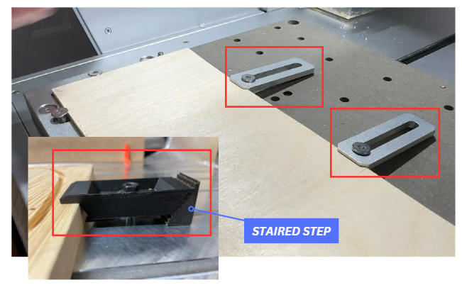
Toe or Top clamps provide a low-profile method of clamping sheet stock from the vertical direction. They offer good reach with a small, clamping area on the material resisting lift caused by endmills.
They are often secured to the bed via a single bolt for quick removal and sometimes a staired step is added for additonal height. However, these clamps are particularly weak in the lateral direction and depending on the design only provide a downforce over a localised area.
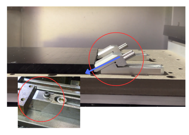
Side clamps
Side clamps apply force mainly in the lateral direction, pushing the stock against a datum fence or fixed jaw. They introduce a small vertical component but are primarily used for securing stock laterally.
Using a combination of tow and side provides lateral location and vertical restraint, creating a more stable setup under cutting loads.
Note: It is critically that we do not over tighten and strip the head of the bolts of the clamp, an easy mistake for first time users. Be firm but gentle.
Milling Vices
Milling vices are most suitable for square and rectangular stock and are the most common work holding method in CNC milling. Tightening the handle drives the movable jaw toward the fixed jaw, generating lateral clamping force that secures the part against a datum face.
Overtightening should be avoided. Excessive force can deform and bow thin parts, lift the workpiece, or damage the vice depending on its design.
Low profile vices often incorporate built in parallels or support features, allowing the part to sit elevated and parallel to the bed while maintaining secure clamping.
Fasteners, Sacrificial material & Counterbores
Fasteners can also be used to secure stock to the bed of the CNC. Bolts are prefered when a threaded bed is available, but their placement is limited by the hole grid and by part geometry (sometimes they don't always line up). The Carvera models use a custom bed with M6 threaded holes at a 45 mm center to center grid.
Alternatively, some cheaper CNCs use a sacrificial bed material (MDF or Plywood), which allows screws to be placed anywhere.
Although our Desktop CNC's use a sacrificial MDF bed that can be replaced, it is important to preserve its flatness and accuracy for all users. Rather than driving screws directly into the bed, designs should allow the stock to be bolted into the existing threaded holes. Repeated screwing and accidental machining into the bed surface will degrade its datum and introduce inaccuracy over time.
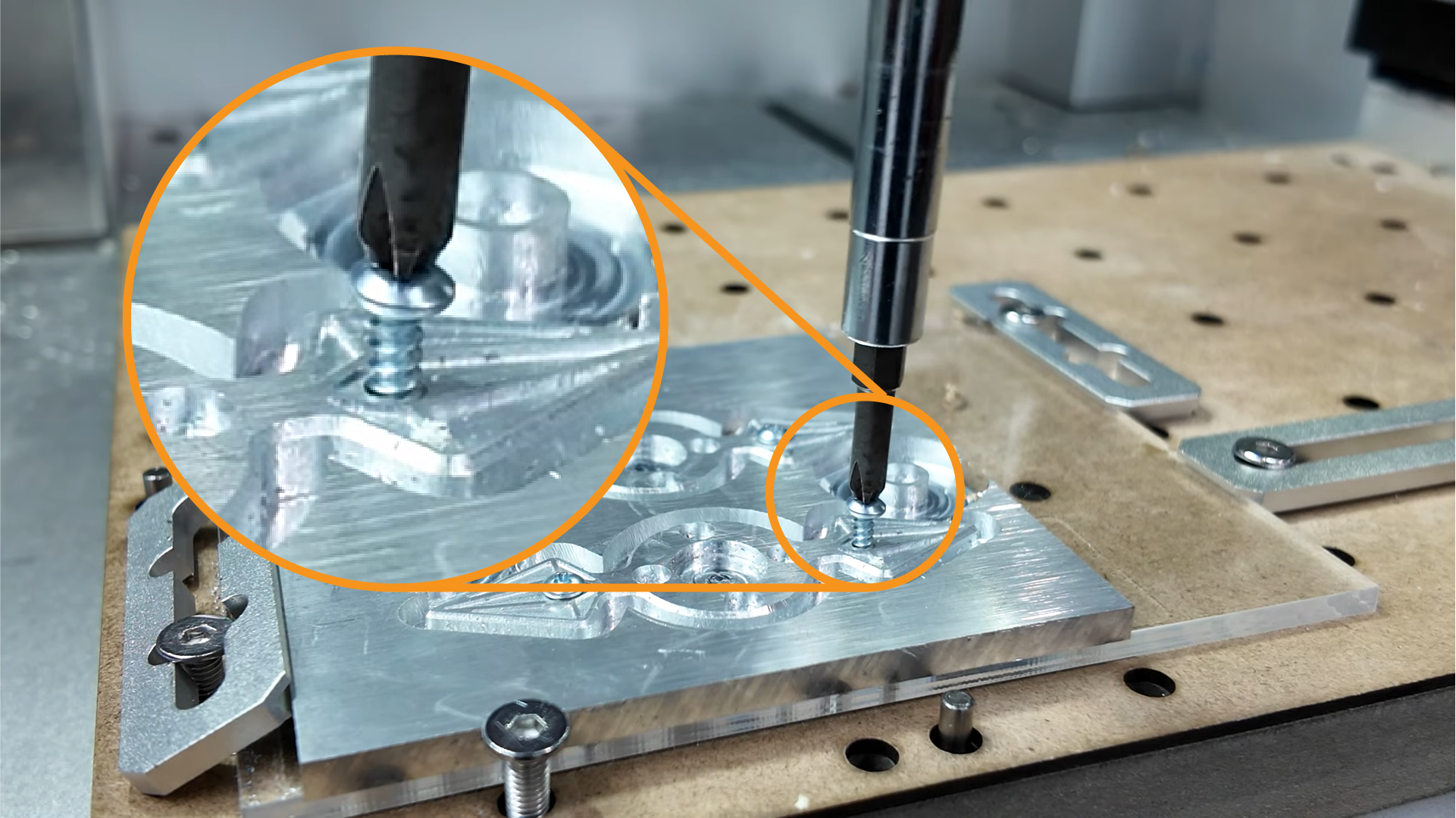

An additonal sacrificial layer, such as acrylic between the stock and bed can be used as an added layer of redundancy (as seen above).
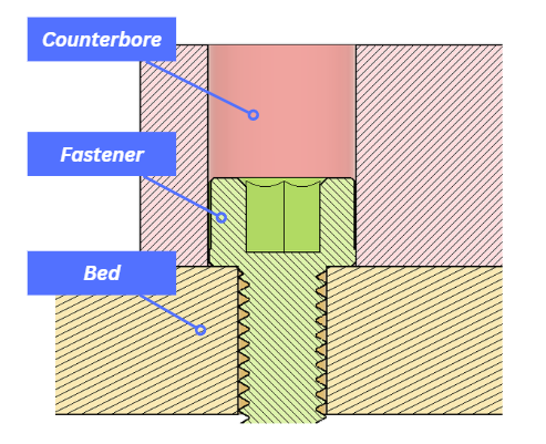
Counterbores are a useful feature to lower the head of fasteners below the critical machine surface. This strategy is often done in two setups or via manual methods, and protects the cutting tool and your fixturing from being machined. An example is shown above.
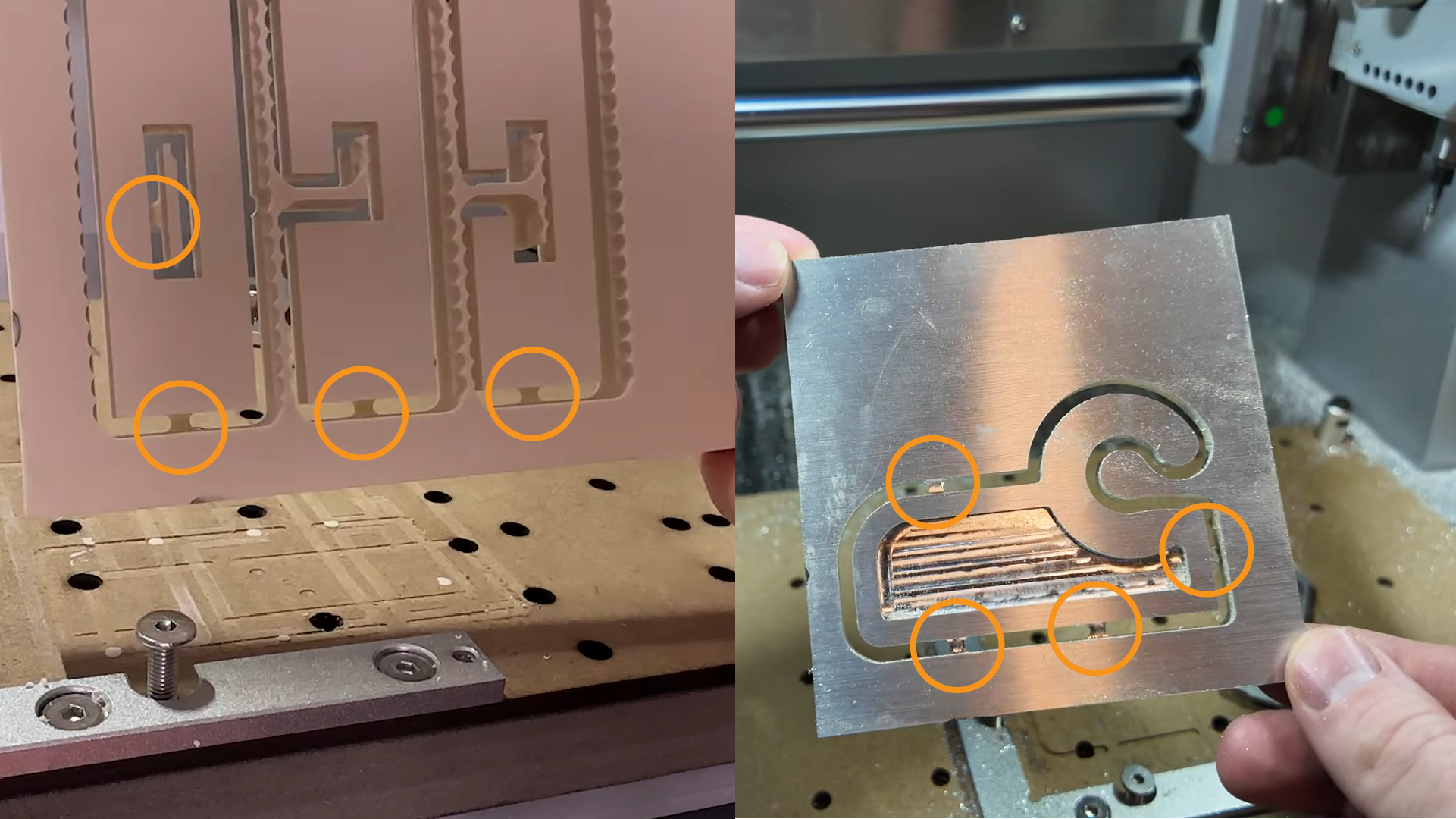
Tabs:
Sometimes, when removing material from stock, it’s necessary to leave tabs to prevent the piece from detaching and potentially flying off. Tabs are small features left to join your design to the mateiral which are removed in post processing.
Tabs are generally required when the design must be entirely separated from the stock and are most common with sheet material.
The following video shows how to set up your tabs within the 2D contour toolpath.
4th-axis Machining:
As discussed previously, an additional axis can be included to achieve more complex designs. Some of the desktop CNC’s also include a 4-th axis module which additionally rotates the part. If you would like to found out more click HERE (LINK NOT MADE YET) to access our learn page (particulalry those Design Built Environment students). The information is considered additional learning and is not covered in this badge.