
For this learning module, you will need:
This module will take you through the basics of performing simulations using Fusion 360. All tutorials and content was made by Autodesk and curated by the UNSW Makerspace Team on this module for educational purposes. Visit the Getting started with simulations in this link to have a complete overview of Fusion 360 simulation capabilities .
To save your progress and designs, log in into your Autodesk account when following these tutorials.

If you haven't done it yet, we recommend you to download Fusion 360 (And well, let's be honest, you should go and check the CAD for Modelling module before getting to this point)
To download and get started on Fusion 360, follow this link to create your Autodesk account and download the software onto your computer.
If you are a current student or an educator, you can have free access to Fusion360 if you use your University email address!
If you want to learn more about Fusion 360, here is the complete product guide.
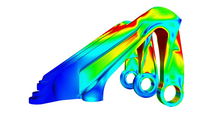
Finite element analysis (FEA) is a computerised method for predicting how a product reacts to real-world forces, vibration, heat, fluid flow and other physical effects. Finite element analysis shows whether a product will break, wear out or work the way it was designed.
FEA works by breaking down a real object into a large number (thousands to hundreds of thousands) of finite elements, such as little cubes. Mathematical equations help predict the behaviour of each element. A computer then adds up all the individual behaviours to predict the behaviour of the actual object.
Finite element analysis helps predict the behaviour of products affected by many physical effects, including:
In this module we will look at linear and non-linear static stress analysis, thermal analysis, thermal stress analysis and structural buckling. For more tutorials and content regarding simulations visit the Test, validate, and explore alternatives section in the Getting Started tutorials from Autodesk Fusion 360.
Before starting with the simulations, there are three main factors that you will need to keep in mind:
Each material has their unique properties which react differently when subject to forces. The basic material properties that need to be known for accurate finite element analysis are:
Each part of your model will have specific interactions with other parts and the environment. These conditions are described as Boundary conditions. In order to simulate as accurate as possible what would happen to your model, you will need to recreate the physical conditions.
Well... It's obvious that we are talking about the force exerted on a surface or body. No room for creativity here!
Static stress analyses are one of the most common types of finite element structural analyses. The component or assembly is subjected to a range of load conditions and the resultant stress, strain, and deformation results analysed to determine the likelihood of failure of the design.
Linear static stress analyses assume that:
The following conditions must be true for the Static Stress analysis to be valid:
Dynamic effects from the loading conditions are not significant. Static stress analysis does not consider inertial effects. However, the mass of the model is used to determine certain static loads, such as gravity and rotational forces.
For more information regarding linear stress analysis follow this link!
A Nonlinear Static Stress study should be used whenever a source of nonlinearity is introduced into the solution, and the assumptions of the linear Static Stress Analysis are no longer valid.
There are four common forms of nonlinearity:
Another distinguishing feature of a Nonlinear Static Stress analysis is that the load is applied gradually over multiple increments. Incremental loading allows the solver to account for changing material stiffness, geometric changes, and changing boundary conditions.
For more information regarding non-linear stress analysis follow this link!
A thermal analysis calculates the conduction of energy across the geometry. To run a thermal analysis, the model material must have a conductance, and a temperature difference must exist for heat transfer to occur. Heat is always transferred in the direction of decreasing temperature. Design parameters can often involve a maximum critical temperature that causes a part failure. If your design is part of a larger design or system it may be of interest to understand and control the heat flow.
Thermal analyses are steady-state heat transfer analyses used to determine the steady-state temperature distribution and heat flow. Heat can be transferred by 3 different methods: conduction through solids, convection through a fluid or gas, and radiation.
This type of analysis requires:
For more information regarding thermal analysis follow this link!
A Thermal Stress study is used to evaluate the stresses induced by some thermal load. For example, will the part warp as a result of some change in temperature? Can the components still be assembled as designed after experiencing the thermal load? Use the Thermal Stress analysis to explore how the stresses from these loads can impact the life of your part.
This type of analysis requires:
For more information regarding thermal stress analysis follow this link
Buckling is the failure of a structural member when subjected to a high compressive stress. Buckling occurs on a long thin column even when the compressive stress is below the material's ultimate compressive stress. Once the geometry has started to deform, it can no longer withstand a fraction of the initial force. Use buckling analysis to determine if a specified set of loads cause buckling and to find the shape of the buckling mode. You can then design supports or stiffeners to prevent local buckling.
Note: Linear buckling analyses provide non-conservative results so it is a best practice to avoid being near the critical load.
Buckling Examples
The following list contains a few examples that Structural Buckling analyses might be appropriate:
For more information regarding structural buckling follow this link

Use this set of video tutorials to convert your Solidwork CAD habits to Fusion360
Download this cheat sheet for keyboard shortcuts!
Also check this out for a list of every single shortcut in Fusion 360!