UNSW Making

Intermediate CNC Milling: Tooling

CNC Milling Intermediate Module 1:

1.1. New tools:


Moving beyond the FEM and Chamfer Mill

In CNC Milling Basics, we covered the Flat End Mill (FEM) and Chamfer mill which service a the majority of tooling in 3-axis CNC machining. In this module we'll introduce three more tools: the Bull Nose Endmill (BNEM) Ball Endmill (BEM) and Engraving Endmill.

CNC Intermediate - BNEM BEM Engrave

Bull Nose Endmill (BNEM):

Bull nose end mills have a flat end with a corner radius, combining some benefits of both flat and ball end mills.

The corner radius strengthens the cutting edge, improving tool life and making the tool useful for finishing flat floors, vertical walls, and shallow 3D features. However, they cannot produce sharp internal corners, as the radius will be left on any internal edge.

removing material FEM
flat_end

Ball End Mill (BEM):

Ball end mills have a rounded cutting end and are mainly used for 3D surfacing, curved profiles, fillets, and complex geometry.

They are not ideal for flat surfaces because the rounded tip leaves small peaks and ridges between toolpaths, called cusps. For flatter finishes, a flat end mill or smaller stepover is usually preferred.

Artboard_3_1TzMa1R.original
Artboard_1_HsO4RTl.max-800x600

Engrave:

Engraving mills are small, pointed cutting tools used to cut fine text, markings, logos, and shallow detail into a surface.

Because the cutting tip is very small and fragile, engraving should be done with shallow depths of cut, light cutting loads, and conservative feed rates. Excessive force can quickly chip the tip, especially in harder materials.

Artboard_7_4DZxRq0.original
Artboard 8

Indexable End Mills

Indexable mills are cutting tools that use replaceable cutting edges, called inserts. When an insert becomes worn, chipped, or broken, it can be indexed to a fresh cutting edge or replaced without removing the tool body from the machine. This reduces setup time, lowers tool replacement cost (as you only need to buy replacement cheaper inserts), and can improve efficiency.

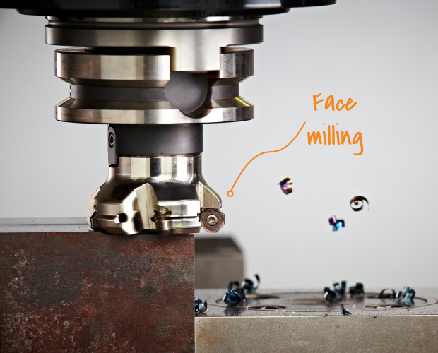
Indexable mills are commonly used for high material removal operations where tool durability and productivity are important. They are especially useful for operations such as face milling, shoulder milling, roughing, and large-area surfacing.

Within the Making Network, the two main indexable milling cutters are face mills and shoulder mills.

Face mills are used to machine broad, flat top surfaces, such as stock faces or reference surfaces. Shoulder mills are used to machine vertical walls, steps, slots, and shoulders, requiring geometry that can cut accurately on both the bottom and side of the tool.

The main advantage of large-diameter face and shoulder mills is that they achieve higher cutting speeds at the insert for the same spindle RPM. Since surface speed (v) is proportional to tool radius (r), larger-diameter cutters can reach highier required cutting speed at lower RPM than smaller tools.

v = ωr
Artboard 1
Artboard 5
facing
Artboard_6_G4p1gp7.original

1.2. Endmill Anatomy: Continued

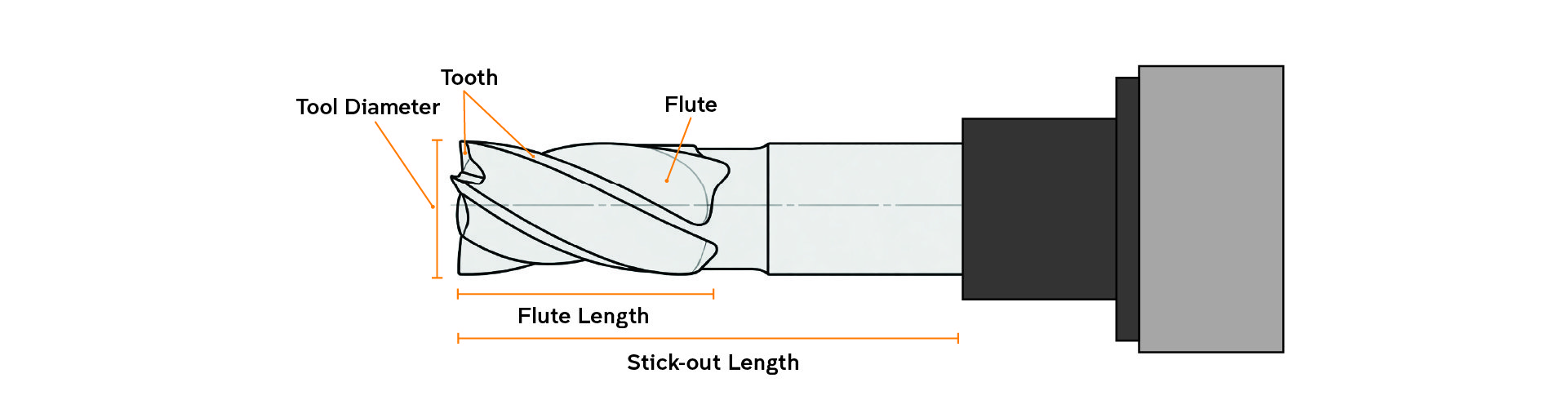
In CNC Milling Basics Module 2.3: FEM Anatomy we introduced the core concepts of an end mill. As a reminder, the topics already covered were:

  • Tooth & Flute
  • Flute Length & Diameter
  • Stick-out Length
  • Life cycle and Tool Wear

In this module we will continue discussing the concepts in greater detail while introducing several new important concepts.

fem anatmoty 2

Flute count continued:

Flute count changes both the cutting edge geometry and the strength of the tool.

Higher flute count tools have more material left in the centre of the cutter because each flute gullet is shallower, know as the core. This gives the tool a larger core diameter, making it stiffer and stronger as seen to the right. Due to the larger core, the cutting edges are also better supported, which can reduce edge deflection and improve longevity. The trade off is that the chip space is smaller, so chips are harder to evacuate. This can cause heat, recutting, clogging, and chip welding, especially in aluminium and plastics.

Lower flute count tools have deeper flute gullets, which creates more chip space. This helps chips clear from the cut and allows a sharper, more aggressive cutting edge geometry. The trade off is that the tool has less core material, so it is generally less stiff and less resistant to deflection. A deeper flute gullet allows for a sharper but less supported cutting edge, making lower flute count tools better for softer, gummy materials where chip evacuation is the limiting factor.

Helix Angle

Helix angle is the angle of the flute relative to the tool axis, as shown on to the right. A higher helix angle pulls chips out of the cut more aggressively, which is useful in materials where chip evacuation is critical, such as most metals. A lower helix angle, or even a straight flute, can produce a cleaner edge in softer materials like wood. Helix angle also creates axial force: upcut tools tend to lift the workpiece, while downcut tools push it down, so tool choice can also affect workholding.

Flute Cutting Direction

The flute cutting direction determines the chip movement. This direction can be identified visually by spinning the end mill clockwise and observing the direction in which the flutes move. When cutting timber, the edge opposite the chip direction will exhibit a superior finish.

  • Up cutters eject chips upward, away from the tool and the fixturing table. and create a upwards force on the stock. They are excellent in metals because they eject chips out of the cutting path to avoid re-cutting them. However, they can rip up the top fibres on timber surfaces, as seen below.
  • Down cutters direct chips downward, reducing strain on the workpiece but potentially causing chip build-up. They create a downwards force on the stock. Down cutters are used in plywood to eliminate tear out of the wood fibres on the top edges. They are usually not suitable in metal because they cause a chip build-up at the bottom of the tool.
  • Compression cutters combine upcut and downcut geometry, producing clean edges on both the top and bottom faces of laminated or sheet materials. Their specialised geometry makes them useful for specific applications, especially plywood and veneered panels.
  • Straight cutters have no helix and no cutting direction, pushing chips sideways, making them primarily suitable for plastics.
CNC Int - fem anatomy 5
up versus down cut

Stick-out length & Tool rigidity:

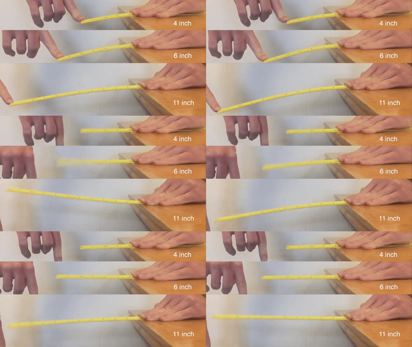
In CNC Milling Basics, we learned that stick-out refers to the length of tool protruding from the collet or tool holder. This distance dictates the maximum reachable depth of machinable features, but it also directly affects tool stiffness, dimensional accuracy, and surface finish.

A cutting tool can be modelled as a simple cantilever beam fixed at the tool holder, with a cutting load, (P), applied near the end of the tool. As shown by the beam deflection equation to the right, maximum deflection increases with the cube of the unsupported length, (L). This means that even small increases in stick-out can significantly reduce tool rigidity.

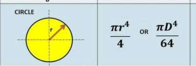
Tool rigidity is governed mainly by two properties: material stiffness, represented by Young’s modulus, (E), and cross-sectional stiffness, represented by the second moment of area, (I).

To increase rigidity, we can increase either of these terms. In practice, this means selecting a stiffer tool material, such as tungsten carbide, and using the largest practical tool diameter for the operation.

Carbide has a higher Young’s modulus than high-speed steel, so it deflects less under the same cutting load. Tool diameter is even more influential because the second moment of area increases with diameter to the fourth power. This means a small increase in tool diameter can produce a large increase in bending stiffness.

Where possible, the shortest and largest diameter tool should be used when machining features with tight dimensional tolerances.


PET_Ruler_Vibrations (2)


max beem delfection

moi circle

1.2. Considerations to design & limitations of tools: Continued


Here's a few useful tips

In CNC Milling Basics we discussed that due to the geometry of the tool and limitations of accessibility of a 3-4 axis CNC machine style, some features and geometry cannot be manufactured. As new tools are introduced, it is important to recognise that each tool has it's own limitations.

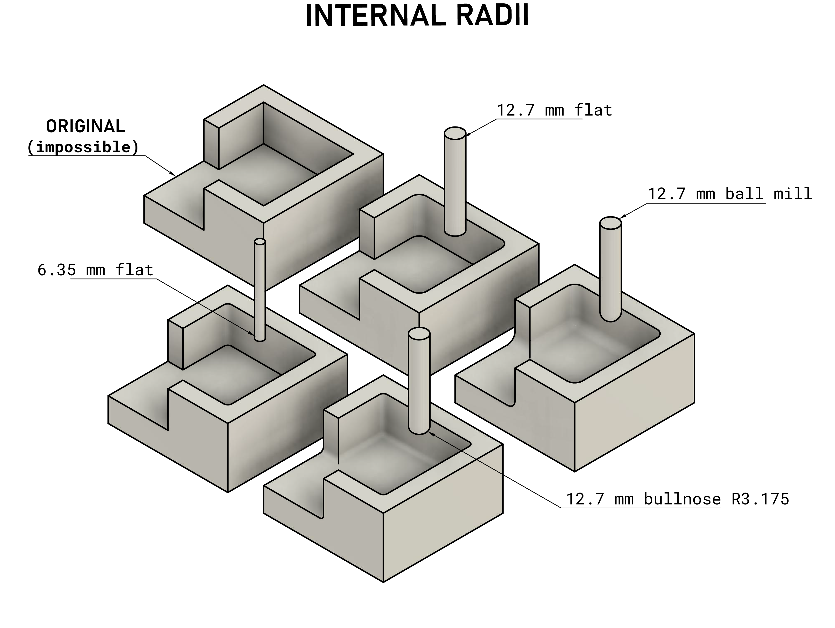
As discussed, due to endmills having a circualr cross-section they inevitably leave fillets equal to the radius of the tool on the internal corners of pockets. Bull nose and Ball end mills additionally leave a fillet on the bottom edges. This detail becomes crucial when attempting to create joinery or complementary parts that fit together seamlessly.

In addition, dogbone reliefs can be machined in a multiple ways, as seen in the example below.

internal radii multiple intermediate tool examples
Dogbones - the solution to internal Radiii

BEM: Cusp height & Stepover

Ball end mills (BEMs) are well suited to machining curved and 3D surfaces as their rounded tip can smoothly follow changes in surface angle.

However and as seen to the right, their geometry leaves a small peak and valley pattern on the surface between toolpaths, known as cusps. The cusp height depends on the tool radius and the stepover between passes. Reducing the stepover lowers the cusp height and improves surface finish, but it also increases the number of passes required, making the operation significantly slower.

StepoverandCuspHeight
Categories: Manufacturing
Tags: CNC