Mastering CAM is a challenging aspect of learning CNC milling, but this module will guide you through the process and help you become proficient.
Before we start, make sure you download and import the tool libraries for Tormach and Symbiosis through their respective links. These machines are available at the Engineering Makerspace located in Kirby. The Fusion 360 website offers instructions on how to import an existing tool library.

_________________________________________________________________________________
Knowing how to design for CNC milling is the first important step.
We will start this section with a beginner's tutorial. The following video provides an overview of CAM, its role in the CNC manufacturing process, and how to set up your CAM. It also guides you through basic operations and what to expect after completing your CAM setup. Please note that in some videos from this module, the CAM tab has been updated to the Manufacturing tab in the latest versions of Fusion 360.
The video provides a detailed guide on creating a new CAM setup and specifying a coordinate system. It also explains the meaning of various options and demonstrates how to use them effectively.
_________________________________________________________________________________
Roughing is the process of removing substantial amounts of material to shape the workpiece closer to its final form.
Typically, roughing operations do not produce a fine finish because removing lots of material causes tool deflection and vibration. It is advisable to perform a finishing pass afterwards to get a smoother and more accurate part. To prepare for this, you should leave some material on the workpiece, which the finishing pass will remove to achieve a smooth surface. This is done by enabling the Stock to Leave feature, which preserves a layer of material for more precise and improved finishing in subsequent passes. The Axial setting specifies the thickness of material left along the Z-axis (vertical walls), while the Radial setting applies to the XY-plane (horizontal surfaces). For an optimal surface finish, it is recommended to leave a material thickness of 0.2 to 0.5 mm.
When roughing, it is crucial to consider the Depth of Cut (DOC) and Width of Cut (WOC). Analyzing these factors helps determine how much material a tool can remove in a single pass, enhancing the efficiency of the roughing process and preventing tool breakage from overly deep cuts. Choosing the right values for DOC and WOC can be challenging. The following are some guidelines
When using a Face Mill, a DOC of 0.5 to 1 mm is recommended for aluminium, and 1 to 2 mm for wood. The width of cut can be about 70% of the width of the tool. For soft plastics, we can take even deeper cuts.
For a flat-end and bullnose mill, the formula WOC x DOC ≤ N x Tool Diameter can be used to calculate these values, where N varies by material—1.2 for aluminium, 1.5 for wood, and 2 for XPS foam. The formula enables you to select values for the WOC and DOC freely, provided that the equation holds. Also, it is important to note that the WOC must not exceed the tool diameter and the DOC must be within the tool's flute length.
Please note, that these values are guidelines and may need adjustments based on specific conditions. For more accurate and specific guides the internet has lots of information and you will need to do your own research.


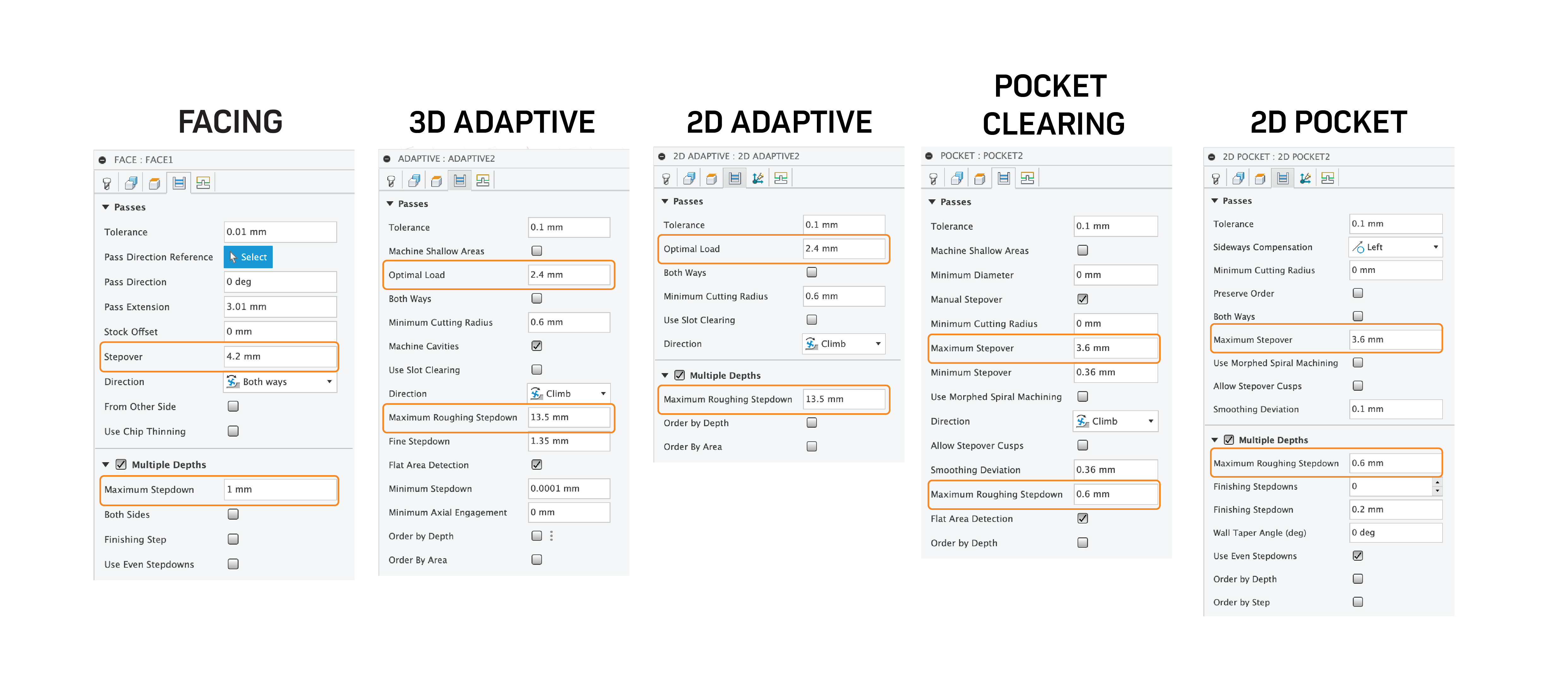
In Fusion 360, to adjust the DOC, search for Maximum Roughing Stepdown or Maximum Stepdown. To modify the WOC, look for Optimal Load or Maximum Stepover. The accompanying image illustrates where these settings can be found for different operations.
Below are videos that provide in-depth insights into adaptive clearing and pocket operations, highlighting the distinctions between these techniques.
_________________________________________________________________________________
This step follows roughing and is typically the final phase in the manufacturing process. It can be omitted if the final surface quality or precise tolerances are not essential. It should only be removing a small amount of material (0.2 to 0.5mm) and finishing passes can be set to pass over the same cut multiple time to ensure the most accurate finish.
Facing is particularly beneficial for enhancing the finish on the top surface of the material. For finishing axial surfaces (vertical walls), you will generally use 2D Contour, and for the radial direction, Horizontal or Flat operations are suitable.

When working with curved surfaces in Fusion 360, operations like Parallel and Scallop are especially useful. Typically, a ball-end mill is employed for these operations. An important factor in achieving high-quality surface finishes is the stepover setting; a smaller stepover results in a reduced cusp height, which improves the finish. However, it's important to note that reducing the stepover can also extend the duration of the manufacturing process, as the tool will need to make more passes over the same distance.
Below, you'll find informative videos that provide insights into obtaining excellent surface finishes with these techniques. While only a few operations are mentioned here, Fusion 360 offers a variety of other options. You are encouraged to explore these further and seek additional information online.

_________________________________________________________________________________
It is primarily used for initial hole creation in CNC machining, employing drill bits designed for quick material removal. It is most suitable for smaller, standard-sized holes where high precision and smooth surface finishes are not critical, making it ideal for rough hole creation.
When drilling holes, it is advisable to perform spot drilling first. This enhances the precision of the hole and reduces wear on your tools. A chamfer mill can be utilized for spot drilling, and this operation can be set up in Fusion 360 under the drilling category. Below, a video is provided to demonstrate how to execute this process.
Boring is used to refine and enlarge holes initially made by drilling or other methods. This technique is essential for machining large or non-standard hole sizes, such as 8.45 mm in diameter, where specific drill bits are unavailable. Boring is particularly valued for its ability to achieve superior finishes and tight tolerances, making it suitable for high-precision applications.
When dealing with very large holes, for example, those over 40 mm in diameter, a pocketing operation can be used. The choice between boring and pocketing for large holes often hinges on factors such as the production time each method requires and the sizes of the tools available.

_________________________________________________________________________________
Sometimes, manufacturing a design with complex geometries in a single setup is not feasible. Therefore, it may be necessary to flip the design to machine the other side. Flipping the part can sometimes be confusing. However, the next video will provide a step-by-step guide on how to do this effectively.
The following video delves into the details of CAM simulation, outlining what to watch for (such as collisions) and how to activate features for a clearer simulation understanding. Remember, simulation is crucial! Never proceed with machining a part without first simulating it. This is the stage where tool collisions can be identified and resolved.
After completing the CAM setup and simulating it, you are ready for post-processing. Post-processing is the final step before machining and it converts the CAM into G-code, which is saved as an .nc file extension. To do the post-processing, right-click on the setup and select the post-processing option. A menu will appear with three key actions:
The choice of post-processor depends on the specific machine you intend to use. In the Engineering Makerspace, we use the following machines and their corresponding post-processors:
Those libraries are accessible via the Fusion Library on the cloud. more information on how to access these libraries can be found on this link. To learn more about G-code, consider reading this article from Autodesk.

_________________________________________________________________________________
Congratulations on completing this module! As we have discussed, mastering CAM is one of the most challenging aspects of CNC milling, and practice is key. To help you with your CAM skills, here is a file you can download to test your abilities. Feel free to use the tool libraries for the Tormach or Symbiosis machines, depending on your preference. If you get stuck, there is a follow-up video that walks you through the process. However, it is highly encouraged to attempt it at least. Remember, practice makes perfect!
Additionally, there are plenty of resources online if you are looking to deepen your understanding of CNC milling. Here are a few helpful websites you might consider exploring:
Video coming soon...