UNSW Making

Haas 5-axis: 3+2 induction

Introduction

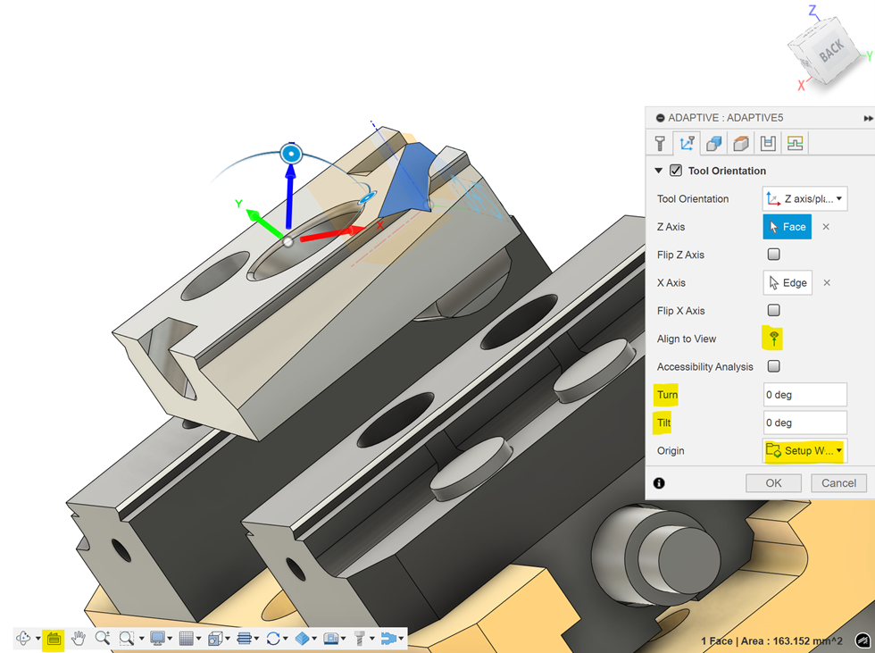
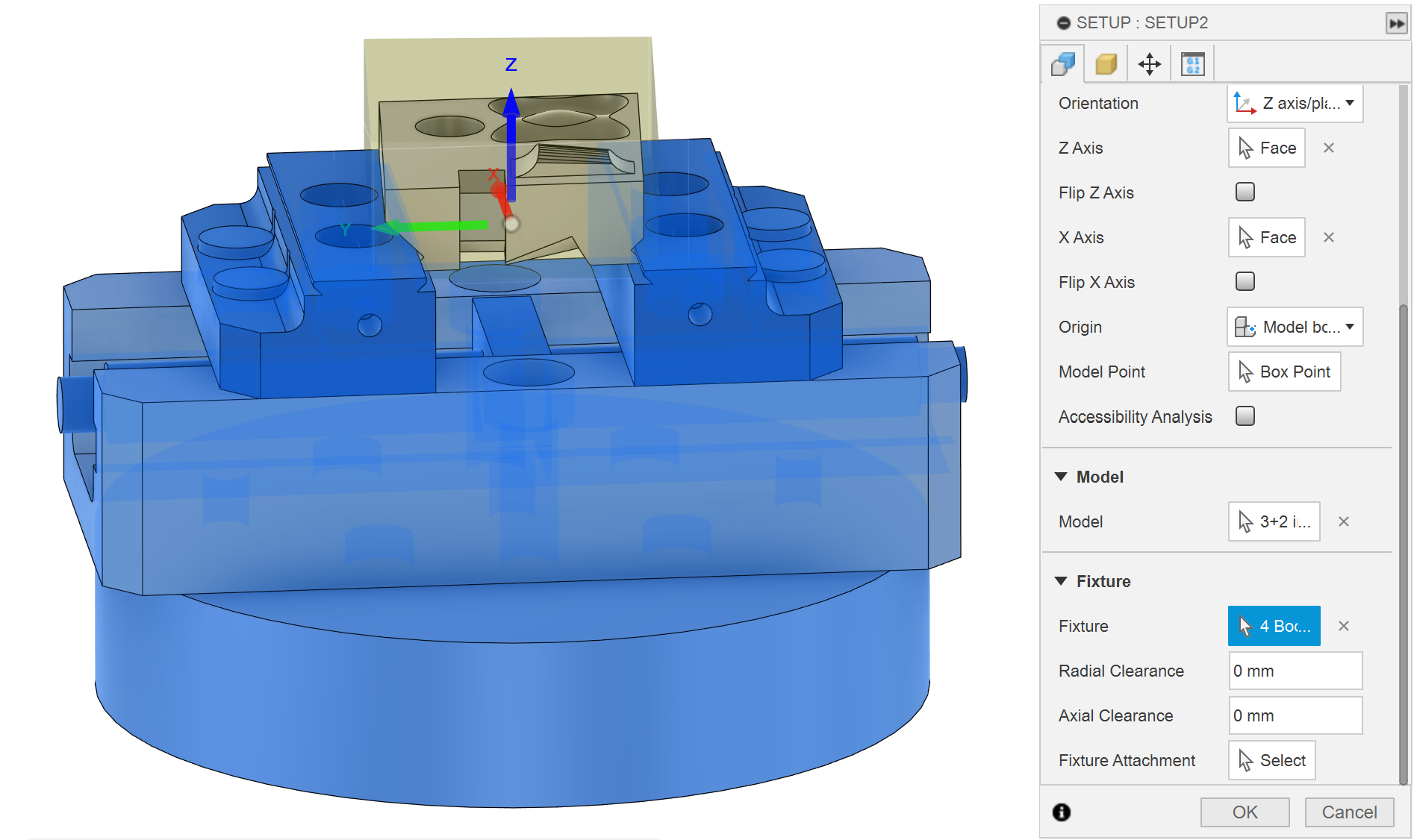
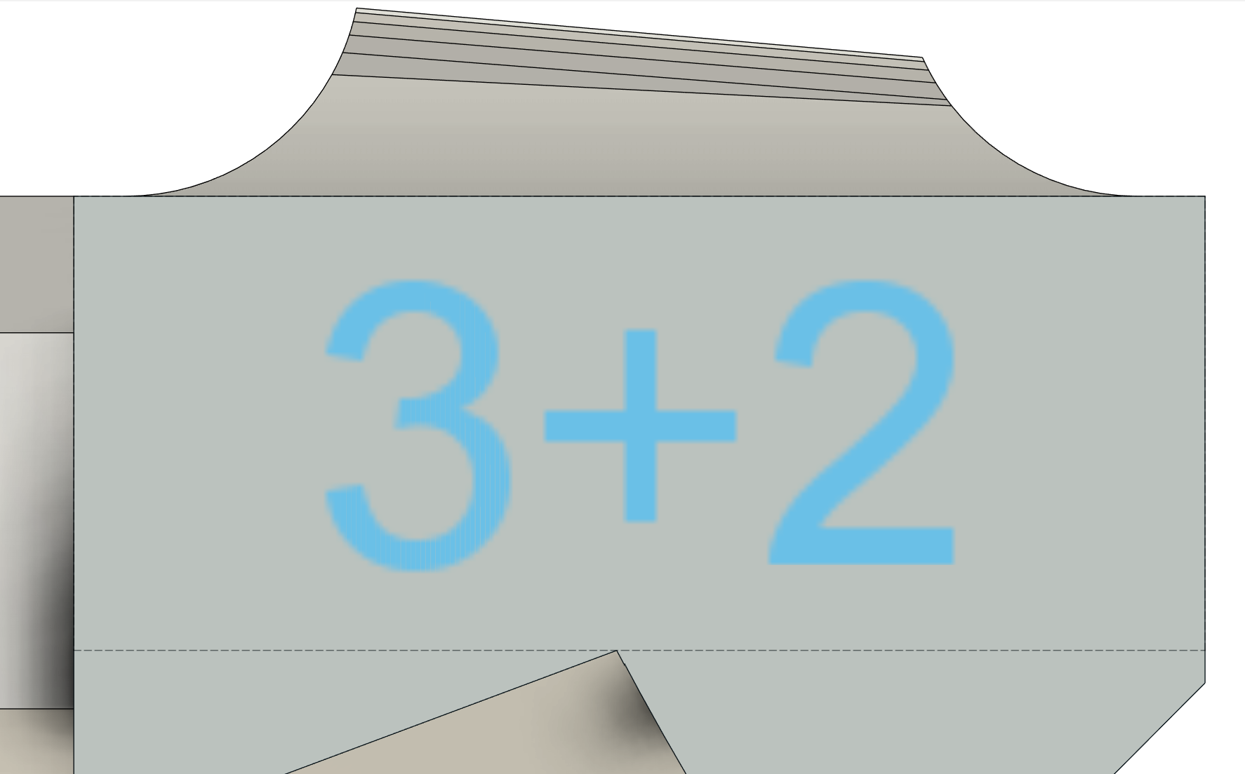
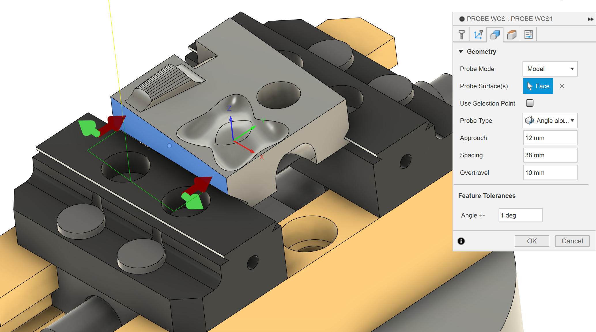
This part is designed to be machined using 3+2 axis machining, which means the B and C axis rotate to an angle, lock and then a 3-axis operation is done. You don't need to use simultaneous toolpaths (where all 5 axes move at once), you will practice that on the next part. It is also an introduction to machining steel, as most people have only used aluminium. Machining steel means you have to learn more about tools and setting speeds and feeds correctly. Finally, this part is designed to show you most of the useful probing capabilities of the machine.

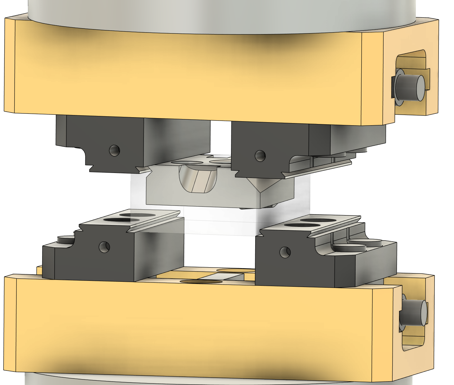
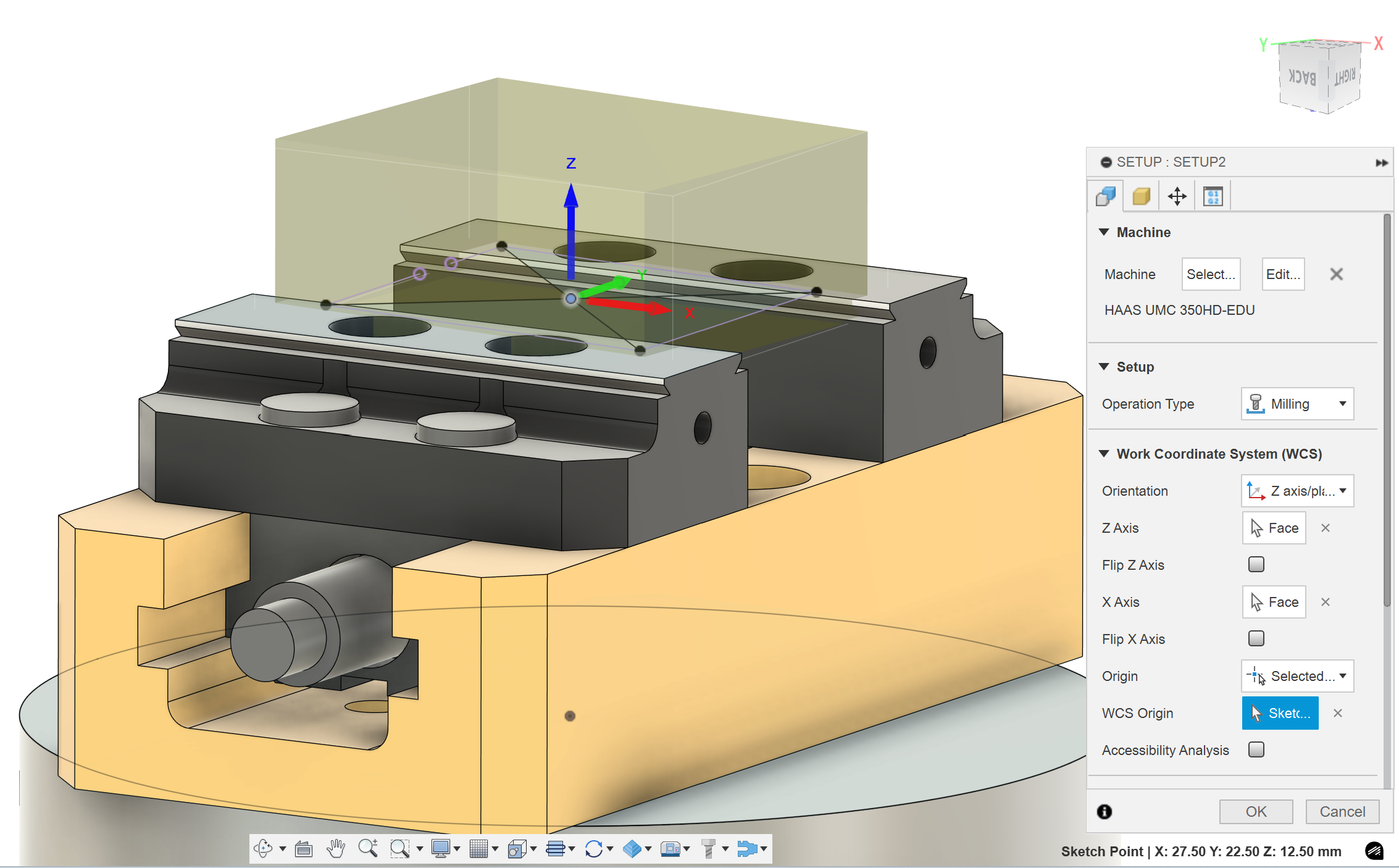
5 axis machining dramatically increases the risk of major collisions that can permanently damage the machine, so everything must be done extremely carefully. This is the easiest machine to crash. All parts of the simulation (stock, holders, tool sickout, work holding vices and the machine model) must be included accurately. The machine is smart enough to stop before the spindle hits the table, but it doesn’t know what work holding or tool you are using so can’t prevent other collisions. You have to prevent crashes by watching the simulation.

Once you have completed the CAM please bring it into the makerspace to get checked by a staff member. If the CAM is good, we will book a time for you to do induction. If there are too many issues with the CAM we will ask you to fix them and return with new CAM. This induction runs by request only, badge training sessions will not appear on the website.

Getting setup

Please download this file and unzip the 5-axis induction folder. This continues the 3+2 induction and the simultaneous induction part files, models of 3 out of the 5 work holding options and the UMC 350 machine model. You can upload the induction parts and work holding models to fusion the normal way, but you will need to import the machine model to the local section of your machine library.

Machine upload
Vice parameters

The work holding files are parametrically designed so you can go into the parameters tab to edit the stock size, parallel height and jaw gap.

To access all of the 5 axis capabilities you will need to enable the manufacturing extension. This has a 30 day time limit but while you are still a student you can renew your access every 30 days so it is effectively unlimited access.

Manfufacutring extension
Haas 5-axis 3+2 CNC induction

When you make a new setup you have to select the HAAS UMC 350-EUD model from your machine library. This will bring the physical model of the machine into your simulations so that you can see collisions before they happen. It also tells the post processer the type of machine you are using, which will affect the generated G-code.

To make the machine rotate for 3+2 machining you need to define new Z and X axis directions, and the post processer will work out what B and C angle it needs to rotate to. This can be done with a tool orientation in most toolpaths. You can set the direction of the Z axis by selecting any plane, cylinder or straight line. There are two useful buttons highlighted in the image: “look at” and “align to view”. You can also manually adjust the turn and tilt of the tool orientation in some toolpaths. Keep the origin setting as setup WCS origin, this will make the machine use a dynamic work offset (the XYZ origin point stays in the same place on the stock but the axis direction rotate).

If you would like more information about tool orientation watch this video.

Haas 5-axis 3+2 CNC induction

When you post process your code there are a few important settings.

  • You need to have the 5-axis machine selected, this changes how the G-code is written to make it suitable for the machine. This should autofill if you include the machine in the setup.
  • The name/number has to be a number, but which number doesn't matter.
  • Don't use "Optionally measure tools at start", it doesn't work and can actually overwrite the length offsets of tools incorrectly. The machine was nearly crashed because of this.
  • Turn on "Optionally cycle tools at start", this puts each tool in the spindle before you run the program, so you can validate you set the tool number correctly. This is important because there is no system to the tool number and it is easy for someone else to change a tool unexpectedly. After all the tools have been validated you can turn on "block delete" and it won't cycle the tools every time you restart the program.
  • Turn on "Use G0". This means all rapid move will be G0 moves. If you don't turn this setting on, some of the rapid moves will use G1 F5000 instead of G0. It is safer to keep all your rapid moves controlled by rapid override so it doesn't switch from rapid to feed unexpectedly.
  • All the other default settings should be correct.

Induction details

  • The stock is a block of mild steel 65 x 50 x 20 mm.
  • You can use the yellow vice to hold the block on both sides. You must model the vice in fusion for both operations to check for collisions between the tools and the vice. The second operation will clamp onto the dovetails that were milled on the side of the part in the first operation.
    • To setup the vices for two operations, import two copies of the vice model into the induction file. Then you can constrain one vice on both sides of the part, for op 1 and op 2. When you make your setups you can select the correct vice as the fixture, and it will ignore the other vice.
    • Make sure to constrain the second vice directly to the dovetail on the part.
    • You can define a radial and axial clearance to the fixture in your setup. Certain smart toolpaths (adaptive, pocket...) will use this to limit where they cut but it can be annoying if they stop your toolpaths from generating.
Haas 5-axis 3+2 CNC induction
fixture setup

Feature guide and requirements

feature 1

Recommended toolpaths: Adaptive, Flat, 2D contour

Work out what orientation would work best.

Make sure to clear most of the material before finishing.

Recommended toolpaths: 2D contour, Trace

This is a simple slot, which should be cut with a simple toolpath. More complex toolpaths (adaptive, pocket, flat…) are more difficult to control and probably won’t do exactly what you need to do.

You have to cut part of the slot in each operation, so this feature is designed to test how well you realign your part in op2.

Haas 5-axis 3+2 CNC induction
feature 3

Recommended toolpaths: Adaptive, Flat, 2D contour

The dovetails have a square corner, so it can be machined with a flat endmill easily.

If you are feeling fancy you can try to use a pattern to duplicate your toolpath from one side to the other. A side note, mirror patterns will reverse climb and conventional.

The dovetail will fit in the vice for op2. Holding onto a dovetail rather than the flat sides of the stock is much stronger, so dovetails can be cut in raw stock for extra work holding strength when machining tall parts.

The dovetails have been designed at a 5 degree angle to the stock, to force you to learn more complex probing for op 2.

Recommended toolpaths: Adaptive, Flat, 2D contour, Blend, Scallop, Flow, Morph

Try to use different toolpaths for the external and internal fillet. The internal fillet has the same radius as the 6mm ball so it is best to finish in with one motion.

For best surface finish, finish the floors and walls before finishing the fillets so that the ball mill is cutting the minimal amount of material.

feature 4
Haas 5-axis 3+2 CNC induction white space
white space

Op 1 Recommended toolpaths: Drill (use deep drilling full retract, slightly slower but safer), Adaptive, 2D contour, Probe geometry (in the inspection tab)

Op2 Recommended toolpaths: Manual NC, Probe WCS (look at the probing requirements section of this guide for more information)

For the 12mm hole you must predrill the hole with the 9mm drill and plunge the 8mm endmill through the predrilled hole. This is the best practice to avoid tight ramping or boring, as descending toolpaths will put excessive stress and wear on the flat end of the tool.

We are also going to use this 12mm hole to automatically probe an accurate XY in the second operation so please cut 1mm deeper than it is modelled.

Make sure there are no plunges in simulation, it is easy to mess up the drilling depth.

This hole needs to be milled using wear compensation to create a precise sliding fit for a 12mm dowel/endmill. It should be within a F6 tolerance, which is between 12.016 – 12.027mm. The hole has been modelled in the middle of that range as 12.022mm. This is a tight tolerance, but the machine should be able to do it. This can be done automatically by probing a semi-finished diameter and using wear offsets.

Useful tolerance websites if you have to do this yourself - https://amesweb.info/fits-tolerances/tolerance-calculator.aspx and https://www.mec-engineering-spreadsheets.com/documentation-area/fit-tolerances-and-applications/

I would recommend doing a spring pass to reduce the taper of the hole.

For the wear offset probing to work the semi finish and finish toolpaths have to be identical. Same stepover, same feed, spring pass, etc.

The stepover for semi and final finishing cannot be too small, otherwise the wear compensation can make the stepovers largely different. Imagine a small 0.05mm stepover, if the radial wear offset is 0.015 then the real stepover of the semi finish pass is 0.05 but the final pass stepover is 0.065, a 30% increase. This increased stepover will increase the tool deflection and then the bore is the wrong size.

To get a nice surface finish (and to learn) you are required to do two feed rate compensations in order to maintain the desired chip thickness for the tool. These will be two numbers that you multiply with your original feed rate.

Firstly, adjust for chip thinning due to the small finishing stepover. https://www.machiningdoctor.com/calculators/chip-thinning-calculator/

Secondly compensate for the difference between actual and effective feedrate due to milling a tight curve.

Recommended toolpaths: Adaptive, Flat, 2D contour

Work out if this should be milled in op1 or op2.

Be carful when you set you bottom and top heights.

Haas 5-axis 3+2 CNC induction
Haas 5-axis 3+2 CNC induction white space

Recommended toolpaths: Adaptive, Flat, 2D contour, Trace

There are a couple different ways to machine this, depending on how much stick out you give your 8mm flat endmill. More stick out is bad because decreases stiffness of the tool by a power of 3 (if you double the stick out the stiffness decreases by 8 times). If you mill the flats with the tip of the endmill you don’t need much stick out, so this is my preference. But it is annoying to create a different operation for each new orientation. Fortunately, you don’t have to. You can create a finishing operation for one side then use a circular pattern (under setup) to do the rest. The flats are each 6 degrees apart. To get the center axis you can create two planes using midplane on some of the flats. Then an axis on the two planes is concentric.

If you don’t want to use the tip of the endmill see if you can find another way to mill this feature, but be careful of collisions.

Recommended toolpaths: Adaptive, 2D contour, Blend, Morph

The fillets here can be milled with the 6mm ball or the 8mm flat. 8mm flat will be much quicker and smoother, but it brings your holder closer to the vice. You should have enough stick out that you don’t collide with the vice but make sure to check in simulation.

Haas 5-axis 3+2 CNC induction

Recommended toolpaths: Pocket clearing, Scallop, Morphed spiral, 3D Contour, Geodesic

This weird thing can be milled in the normal orientation, but cutting with the tip of the ball mill is not ideal. It causes the ball mill to wear much faster, increases the chance of chipping or breaking a tool and will leave worse a surface finish.

Fortunately, we are using a 5 axis, and so we don’t have to use the tip of the ball mill if we rotate the part. Try using the slope setting that is in most 3D finishing toolpaths to avoid cutting with the tip. Then you can machine the entire surface with two or more orientations.

It is also sometimes useful to use the avoid surfaces setting or the model setting (with the setup model not included) to prevent the tool from machining the surrounding flat area. These are both in the geometry tab of certain toolpaths.

Make sure to do a roughing operation with the ball mill before finishing. A roughing operation with the flat endmill leaves a lot of stock so your finishing pass depth of cut will be inconsistent, which creates worse surface finishes.

In this scenario pocket is better than adaptive. Pocket is designed for small stepdown and large stepovers and will allow slotting. Adaptive is designed for large step downs and small stepovers and won’t allow slotting. Try both and see what toolpath seems more efficient.

Recommended toolpaths: Engrave

Please engrave 3+2 into the side of the part.

This is designed to force you to rotate the vice to a 90 degree angle, so that you can see how important tool clearance and accurate holder and vice simulation is.

If we don’t have any coated engraving tools you can do it with an uncoated endmill but make sure to label it for steel, because it will be too dull for aluminium afterwards.

Haas 5-axis 3+2 CNC induction

Probing requirements

In order to learn how to use the probe there are several probing requirements when setting up op2. The first three steps you will do manually during the induction to locate a rough origin. Steps 4 to 6 should be prepared before the induction in your CAM program and will use the rough origin to probe an accurate origin.

Step 1

When you flip the part for operation 2, it will clamp into the vice at an angle. During the induction you will manually use the corner angle probing routine on the machine to roughly measure this angle on the raw stock edges. Then you will manually update G54 C origin and rotate the part to align with the XY axes.

Step 2

Once the part is aligned, you will manually probe a rough G54 XY origin in the center of the part using the top hat sides (the uncut stock). This origin is good enough to do roughing operations with stock to leave but not accurate enough for finishing operations.

Step 3

You can manually probe Z on the top surface of the jaws. This isn’t perfect but it is accurate to about 30um. It isn’t easy to probe on the inbuilt parallels of the vice because they are too small.

You will need to create a sketch of this custom origin point at the height of the jaws and in the center of the part.

WCS op 2 3+2

Step 4

You can use the rough origin to mill off the top hat so that you can probe a more accurate origin. In your CAM you should setup an in-process probing to measure the accurate part angle on a machined surface and update the G54 origin.

When in-process probing an angle the machine controller will write the measured angle to the C axis G54 origin, then rotate the part to G54 C0. This rotation makes the part parallel with the axis. The vices in the 5-axis are also not trammed correctly so it is sometimes important to probe the angle on the raw stock and very important on flip operations.

The Haas 5-axis UMC doesn't normally use G68 rotation.

white space Advanced CNC milling

Step 5

In your CAM program, insert manual G-code to call “G54 B0. C0.” which will rotate the part to the newly probed C0 origin.

Fusion won’t write B or C axis moves unless it is rotating the part (think tool orientation)! This means that after we probe the accurate C angle the program will not automatically rotate to C0. This is super dangerous because if your next program doesn’t specify a rotation it will just stay at the wonky angle you probed at. So the next operation will run expecting your part to be at C0, even if it is not. This could cause plunging, crashing, or bigger than expected cuts which can break a tool or damage the machine.

I think “action” Manual G-code is safer than “pass through” because it only accepts correct G-code.

Step 6

In your CAM program, automatically probe an accurate XY origin off the 12mm circular hole and update the G54 origin using in process probing. You have to do this after probing your accurate angle, otherwise the hole will be in the wrong position and the XY origin will be wrong.

Probe macro variables

When the probe takes a measurement in writes the output to a macro variable. Depending on the probing routine it will write to a different macro variable. Knowing where to find this information is super useful because you can use the probe to measure the size of features such as bores, bosses, and slots.

Haas 5-axis 3+2 CNC induction

Related Badges