On machines with an connected wireless probe you can write probing routines in your CAM. These can be used to update tool wear, probe a work coordinate system, or measure your part.
It is possible to use the probe to measure the size of a feature manually or automatically. To measure manually simply run a normal probing routine from the machine controller and the machine will record the size of the probed feature (where it displays that information varies on each machine).
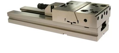
To measure automatically use the "probe geometry" toolpath in Fusion. This will output the size of the feature to the same place as manually probing but will not interrupt the running of your program. Probe geometry also has the advantage of being able to stop the program if the position of size of the feature is out of a specified tolerance.
On the Haas machines the probe will output information to the macro variables shown in the table. The most useful is #188, which is the size of the last probed feature.

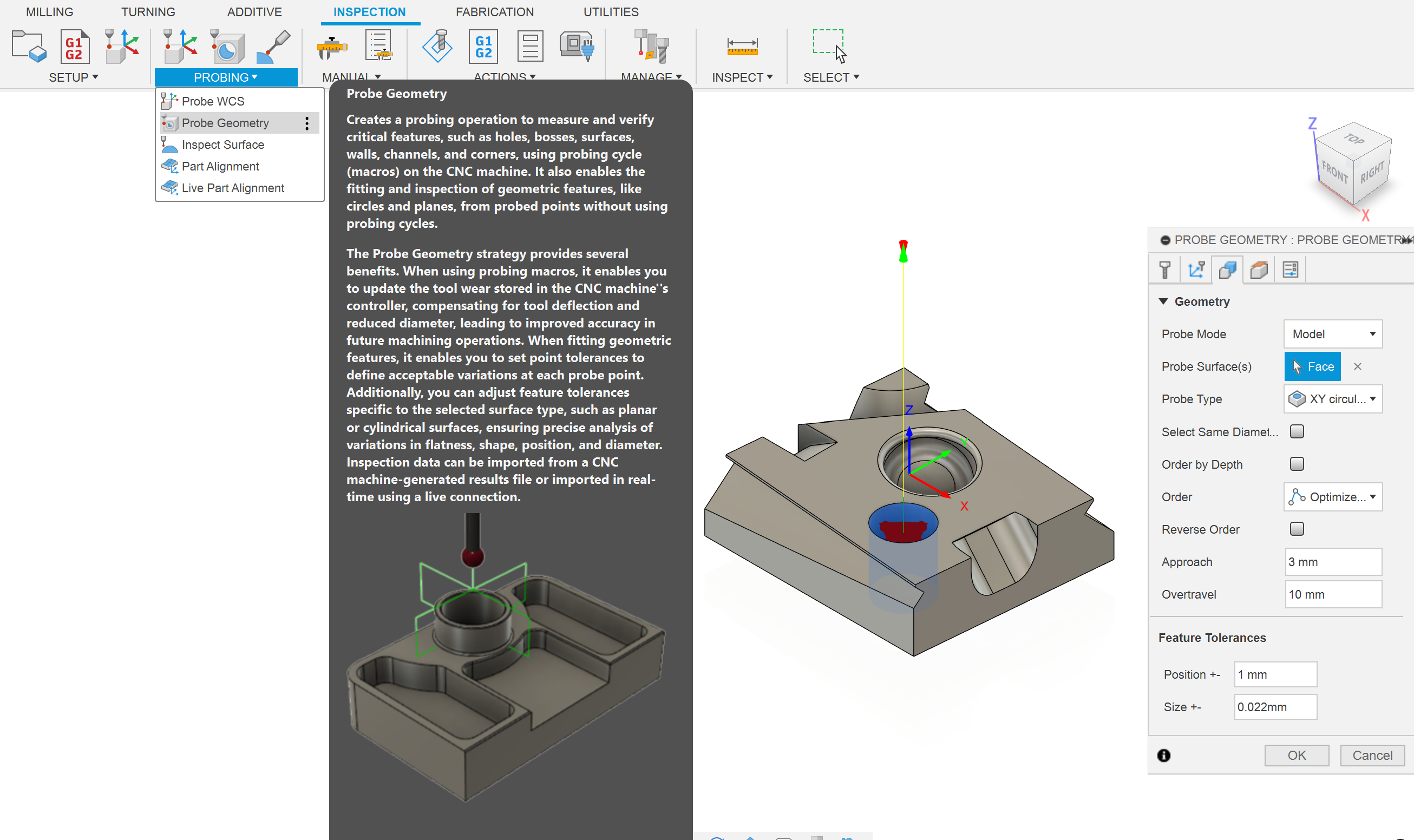
The Datron writes the size of the probed feature at the top of the screen.
Wear offsets are used to make tight tolerance features. A wear offset is the difference between the nominal size of a tool and the size at which it cuts. There are wear offsets for length and diameter but the diameter wear is much more useful.
Wear offsets are used to account for two things: the actual diameter of the tool and the tool deflection during cutting. A 10mm endmill is not perfectly 10mm, and its diameter and length can actually reduce as it get worn down (hence the name wear offset). The real diameter of a tool can be measured with some tool length probes. Secondly, tools experience a sideways cutting force that causes them to bend slightly. For parts without strict tolerances this bending is negligible but for tolerances under 0.1mm it can be important. The amount of deflection depends on the cut, so an identical test cut has to be done before the final cut.
You can use the spindle probe to measure the size of features on your part. Then the wear offset is calculated as the difference between the actual size and the desired size. The next cut will be more accurate. Using wear offsets compensates for dimensional inaccuracy and deflection and can allow for hitting tight tolerances.
You can include in process work coordinate system probing routines in your CAM to probe a new origin. In process means that the probing happens during your program, rather than being done by the operator before the program runs.
The two common uses of in process WCS probing are flip operations and repeat parts. During flip operations a top hat of excess stock initially prevents access to the machined sides. You can manually probe the raw stock for a rough origin, mill off the top hat with stock to leave, probe an accurate origin, and then continue milling. When running lots of the same part you can program a probing routine that will find the new origin automatically, so long as the new part is close to the old origin.
Fusion in process WCS probing routines works on the Haas and Datron machines. On Haas it will overwrite the current WCS (usually G54) which means the new origin is automatically saved.
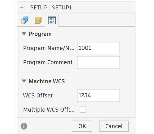
On Datron it sets the current WCS to the new position but doesn't save this position. This is fine for the majority of Datron users, if you are just making one part with one origin. However, if you are using Datron's named WCS system it doesn't overwrite the active named WCS zero position. To overwrite a named WCS you have to choose a WCS name that is a number and make the WCS Offset in the Fusion setup the same number.
In addition to programming in process probing routines in Fusion, you may program them on the Datron. This is more advanced and rarely necessary.
Whenever you flip your part you will have some angular misalignment, determined by how well trammed your vice is to the X axis. Normally this misalignment will cause locational inaccuracy between top and bottom features. You can reduce the error by tramming the vice or you can compensate for the error with G68 rotation!
G68 rotates the CAM program by a set angle around a set point. The means you don't need to tram your vice perfectly and you can make more accurate parts.
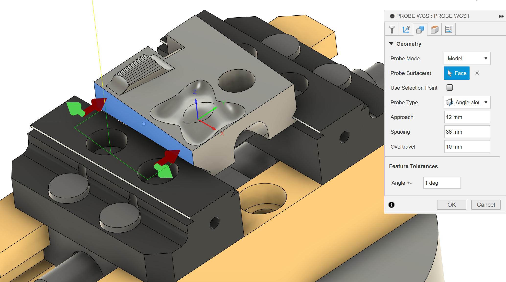
To use G68 you need to probe the rotation angle. You can do this with a probing macro on the machine controller or with a probing WCS routine in Fusion. If you manually probe the angle you need to write Manual NC code to use the G68 rotation, which is more difficult. If you use the in-process WCS probing routine in Fusion for an angle it will automatically add a G68 rotation in the code after the probing.
This angle compensation works slightly differently on each machine. Tormach doesn't have the capability for G68. Datron doesn't have a trammed vice so it automatically probes the angle and uses G68 on every part. The Haas Mini-Mill uses G68 normally. The Haas 5-axis UMC doesn't normally use G68, after in-process probing an angle the machine controller will write the measured angle to the C axis G54 origin, then rotate the part to G54 C0. This rotation makes the part parallel with the axis. The vices in the 5-axis are not trammed correctly so it is sometimes important to probe the angle on the raw stock and very important on flip operations.

Part alignment uses the probe to measure the location of a bunch of arbitrary points on an existing part to work out its position. It is use to find the origin on parts without square or flat edges, like 3d prints, castings or fancy geometry.
The instructions are in the Probe/ETS page of the machine.
Use a ring gauge to set the effective tip diameter.
There is a probe calibration routine on the machine, that will mill a pocket of known location and size. Then it will probe the pocket to set the probe tip location and diameter.
The first video is the standard probe calibration
The second video has an extra probe calibration than enables vector probing. Vector probing allows for probing in direction other than the X and Y axes.