UNSW Making

Injection Moulding Basics

What is Injection Moulding?

What is it?

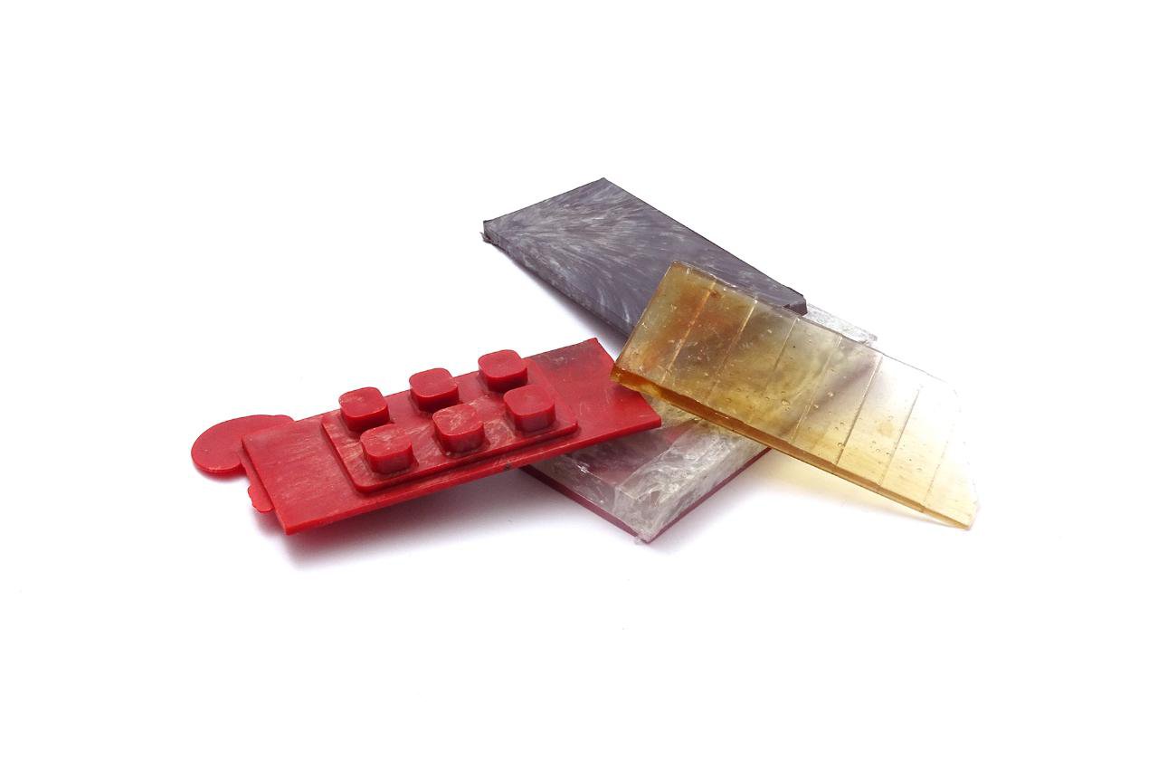
Injection moulding is a manufacturing process that melts, injects and sets plastic into a metal mould. The plastics used by injection molding processes are relatively cheap and can be used to achieve a wide variety of properties, so injection molding is popular for creating many packaging and consumer products, like LEGO!

Commercially, injection moulding offers a flexible, consistent and cost-effective process of manufacturing that allows for rapid production of parts in a range of materials. Once the process has been set up and tested, machines can produce thousands of items per hour and once the mould is created (which is the most expensive element) the cost of production per component is relatively low.

25H.jpg

Desktop Injection Moulding

Here at UNSW we have 2 CR Clarke desktop injection moulders great for learning, testing and experimenting with the process!

Designing for Injection Moulding

Anatomy of a mould

Draft Angles


Injection Moulding-04.png

Draft Angle

Draft angle is a taper applied to the vertical walls of the component to be moulded to assist with releasing the part. Walls without draft angle may become stuck in the mould and will have drag marks on their surface.

A minimum draft angle of 2 degrees is recommended but larger draft angles may be required on taller features.

Injection Moulding-08.png

Wall Thickness

To avoid warping and sink marks on the part as the melted material cools down it is important to have uniform wall thicknesses and avoid thick sections if possible.

If sections of different thicknesses are required, make the transition as smooth as possible using a chamfer or fillet. This will allow the material to flow more evenly through the mould.

A wall thickness between 1.2mm and 3mm is usually a safe value for most materials.

Injection Moulding-09.png

Wall thickness cont.

Hollow out thick sections

Thick sections can lead to various issues such as warping and sinking. Reducing the maximum thickness of the design can be achieved by making the thicker sections hollow is essential. To improve the strength of these sections, ribs can be used to create structures that are of equal strength and stiffness but with reduced wall thickness and weight.

Injection Moulding-07.png

Ribs

When even the maximum recommended wall thickness is not enough to meet the functional requirements of a part, ribs can be used to improve the strength and stiffness of a part.

When designing ribs, use a thickness equal to 0.5 x the main thickness, define a height smaller than 3 x the rib thickness and use a base fillet with a radius greater than 1/4 x the rib thickness. Also make sure to add draft angle!

Injection Moulding-05.png

Bosses

Bosses consist of cylindrical projections with holes designed to receive screws and other fasteners and assembly hardware, they are very common in injection moulded parts as they are used as points of attachment or assembly.

The outer diameter of the boss should be 2x the nominal diameter of the screw or insert and its inner diameter equal to the diameter of the core of the screw.

Injection Moulding-11.png

Undercuts

Undercuts refer to part features that cannot be manufactured with a simple 2-part mould because material is in the way while the mould opens or during the ejection of the part. Avoiding undercuts all together is usually the best options as they add cost, complexity and maintenance requirements to the mould.

Redesigning the part to remove undercuts or moving the part line can be possible solutions to make the design more feasible.

Injection Moulding-08.png

Round All Edges

The uniform wall thickness limitations also applies to edges and corners; the transition must be as smooth as possible to ensure good material flow through the mould.

For interior edges, use a radius of at least 0.5 x the wall thickness. For exterior edges add a radius equal to the interior radius plus the wall thickness to ensure constant thickness everywhere. This can also help to stop stress concentrating in the sharp corners which can cause weaker parts.

Injection Moulding-06.png

Text and Symbols

Text is a very common feature that can be useful for logos, labels, warnings and instructions.

When adding text choose embossed text over engraved text as it is more economical when creating the mould. Raising the text 0.5mm above the part surface will ensure the letters are easy to read.

Injection Moulding-10.png

Tolerances

Injection moulding typically produces parts with tolerances of +/- 0.25mm. Tighter tolerances can be possible in certain situations but increase the cost of manufacture dramatically.

Materials

Injection Moulding at the DFL

Common Issues

words words words

Take a look at the following guide from 3D Hubs to see some of the most common defects that can happen when moulding.

Warping.jpg

Warping

When certain sections cool (and as a result shrink) faster than others, then the part can permanently bend due to internal stresses.

Parts with non-constant wall thickness are most prone to warping.

Sink Marks.jpg

Sink Marks

When the interior of a part solidifies before its surface, a small recess in an otherwise flat surface may appear, called a sink mark.

Parts with thick walls or poorly designed ribs are most prone to sinking.

Drag Marks.jpg

Drag Marks

As the plastic shrinks, it applies pressure on the mold. During ejection, the walls of the part will slide and scrape against the mold, which can result to drag marks.

Parts with vertical walls (and no draft angle) are most prone to drag marks.

Short Shots.jpg

Short Shots

Trapped air in the mold can inhibit the flow of the material during injection, resulting in an incomplete part. Good design can improve the flowability of the melted plastic.

Parts with very thin walls or poorly designed ribs are more prone to short shots.

Knit Lines.jpg

Knit Lines

When 2 flows meet, small hair-like discolorations may develop. These knit lines affect the parts aesthetics, but also they generally decrease the strength of the part.

Parts with abrupt geometry changes or holes are more prone to knit lines.

Title Image.jpg

Troubleshooting

Guide

Other Resources

Categories: Manufacturing