It is important to check that your tool isn't going to collide with the work holding before you run every program. Fortunately it is super easy, and there are many ways to do it. The most reliable method is to handle jog a tool to the deepest point of your program and carefully move it over the vice.
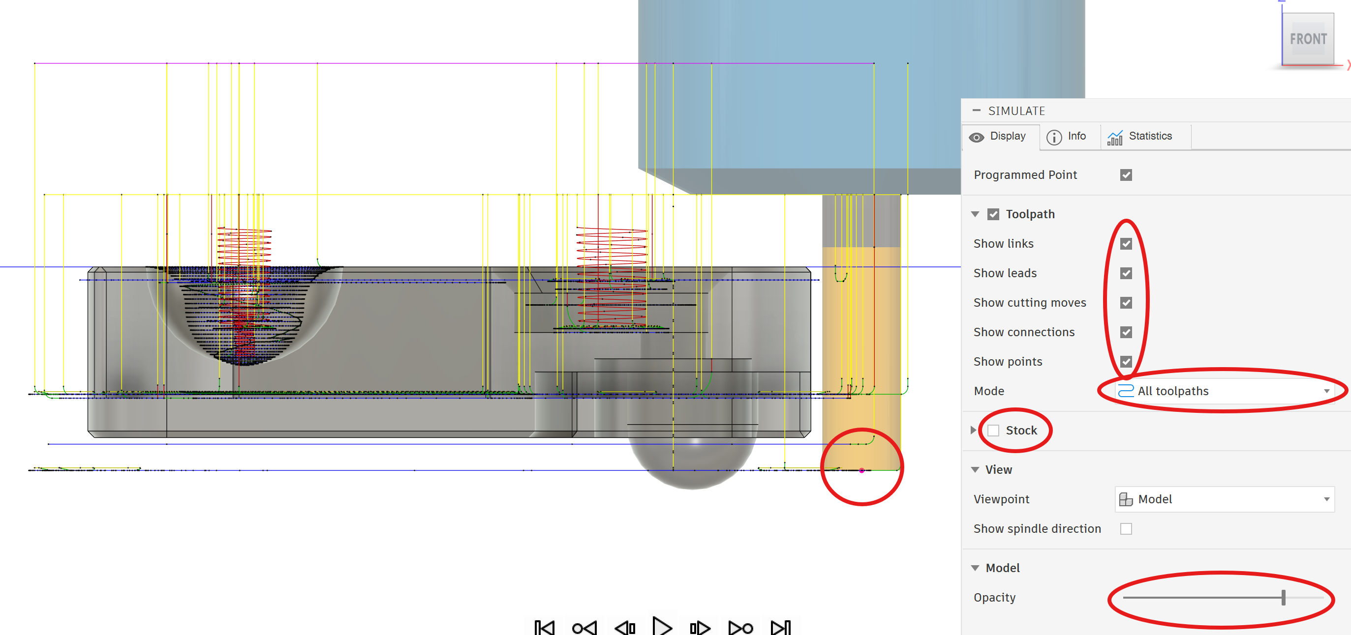
Start by probing your origin and all your tools. Then, to find the deepest z of your program you can simulate the toolpath. In simulation make all the toolpath visible and show all the different parts of the toolpath. It can be helpful to turn the stock off and make the model transparent so you can see all the toolpath at once. Then you can click on the lowest point in the toolpath and the simulation will jump to that point.
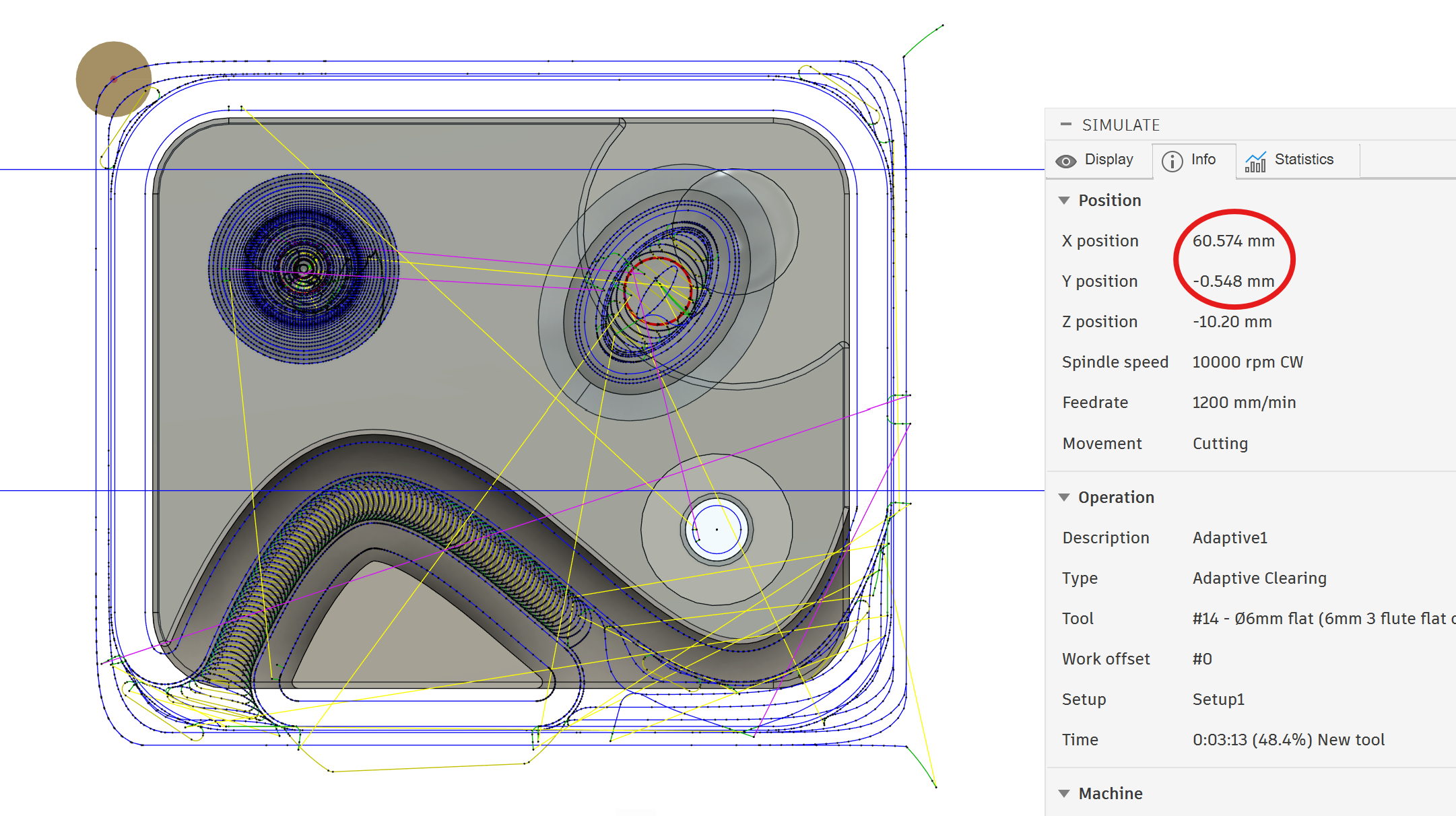
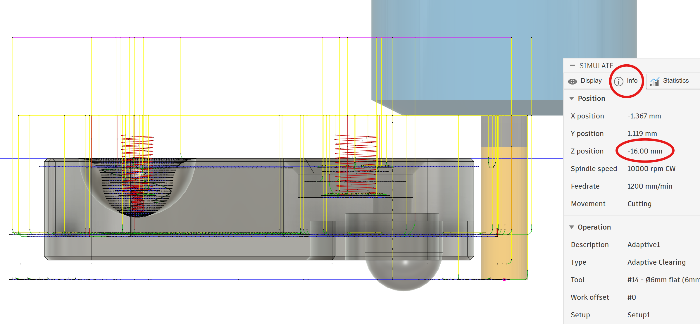
Once you are at the deepest part of your toolpath go to the info section of the simulation to find the z height.
Use the handle jog to move the tool to the deepest z somewhere away from the vice. Then slowly move towards the vice, while checking if the tool with collide. When it gets close a piece of paper or a ruler can help you check if it will collide.
If there is minimal gap, check both sides of the vice jaws, because they can be different heights.
You can use the same method to check clearance to other objects in x and y: for example if there is a second vice mounted in the machine.