Changing your setting defaults
Saving your own default settings in each toolpath can make CAM faster and reduce errors. There are two types of settings you can save: parameter values, and whether to enable options.
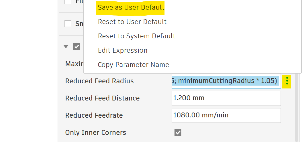
Parameter values are easy to save: simply click on the three dots next to the text box and select Save as User Default.
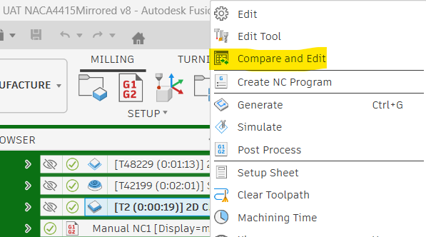
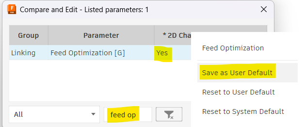
Saving which options are enabled by default is slightly more complex. You have to right click on the toolpath and select Compare and Edit which opens a menu with all the settings in a list. Search for the option you want to change, choose Yes or No, then right click to Save as Used Default.

Useful setting defaults
Enable Feed optimisation for most toolpaths to avoid chatter in tight corners. There is more information about what feed optimisation is doing in the Feed and Speed module. Under feed optimisation set:
Reduced Feed Radius = max(tool_diameter * 0.05; minimumCuttingRadius * 1.05)
Reduced Feedrate = tool_feedCutting *(reducedFeedRadius*2)/(tool_diameter+reducedFeedRadius*2)
Enable Order By Area in 3D Adaptive. This normally makes it faster.
Decrease the Optimal Load for 2D and 3D Adaptive to tool_diameter * 0.05. This means that if you forget to set the optimal load the default is very conservative and will not damage the tool.
Enable Multiple Depths in the Face toolpath so you don't accidently face a huge amount of stock.
Enable Multiple Depths in the 2D Contour toolpath so you don't accidently cut deeper than the flute length.
Increase the Minimum Cutting Radius to tool_diameter * 0.1 for 2D Contour. This prevents the toolpath from having a sharp corner.
If your normal order of operations is rough everything, floor finish, then wall finish you can change Horizontal and Flat toolpaths to enable Stock to Leave by default. Then make the Axial Stock to Leave 0 and the Radial Stock to Leave match (or be slightly larger than) your default roughing stock to leave.
Enable Machine Over Holes in the Flat toolpath.
Enable Spiral in the Flat toolpath.
Increase the Stock Offset above 0 in the Face toolpath to ensure it always faces more than the stock.
Make "Deep drilling - full retract" the default cycle type for drilling. This is the safest cycle type for HSS drills. However you need to change it to "Drilling - rapid out" when using carbide drills to avoid pecking.
Manufacturing extension
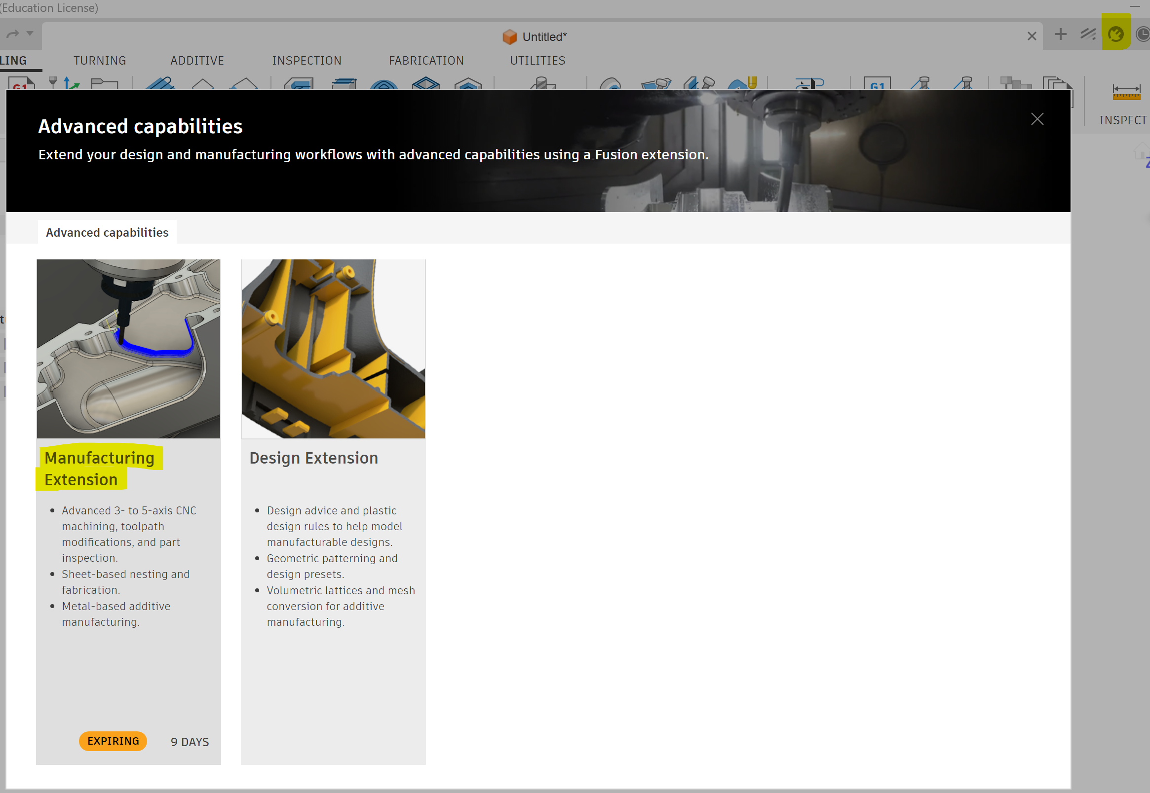
There is a manufacturing extension in fusion that gives you access to more toolpaths, 5-axis toolpaths and the modify toolpath section. It expires every 30 days but can be renewed endlessly with a student license. Click on the plug icon in the top right of Fusion to enable the manufacturing extension.
Manufacturing display options
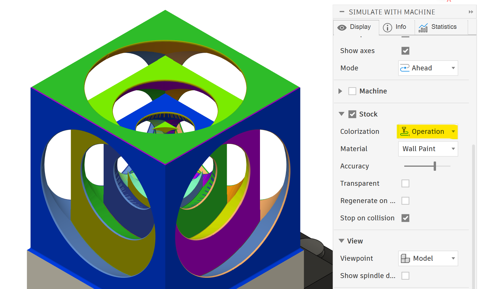
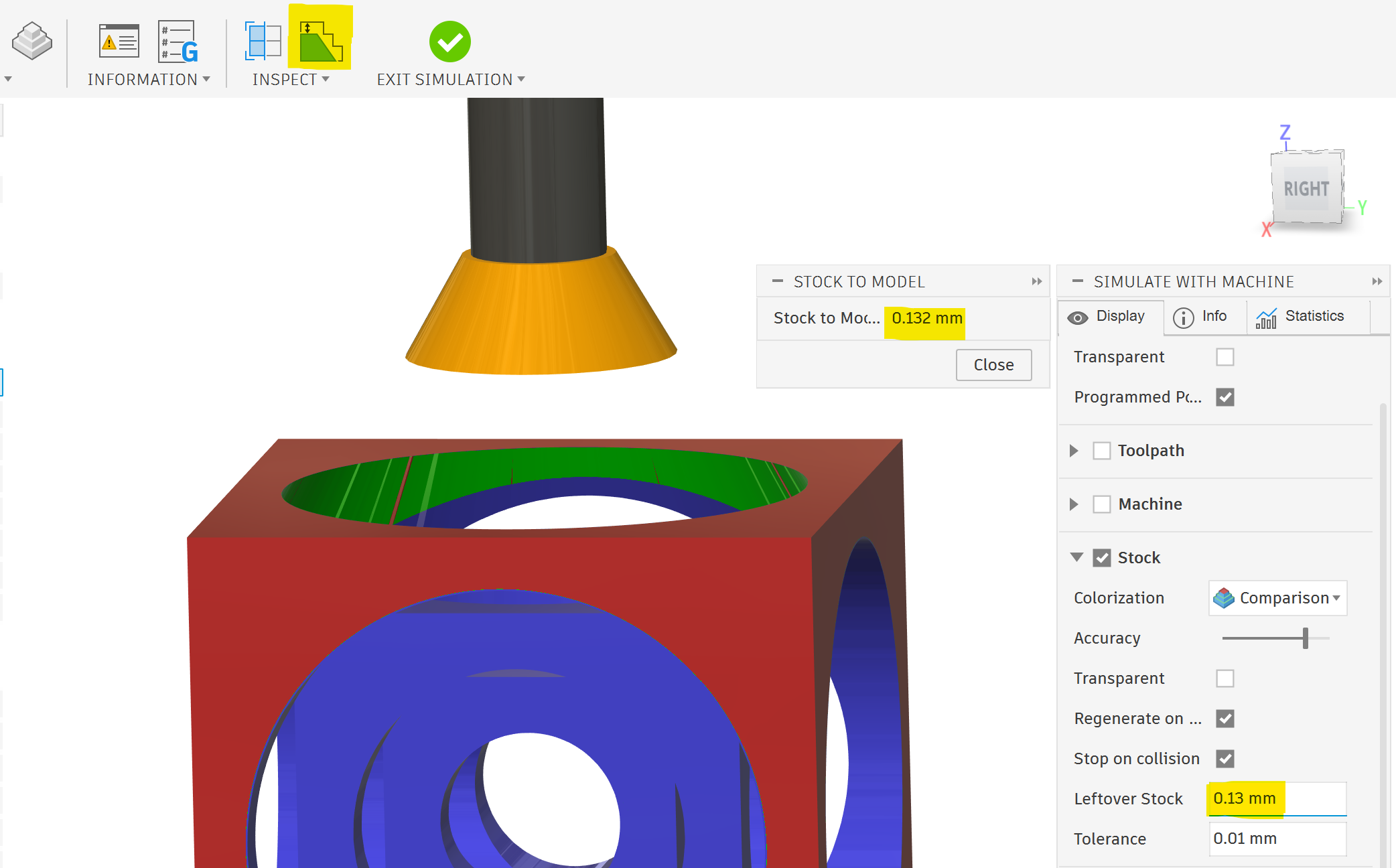
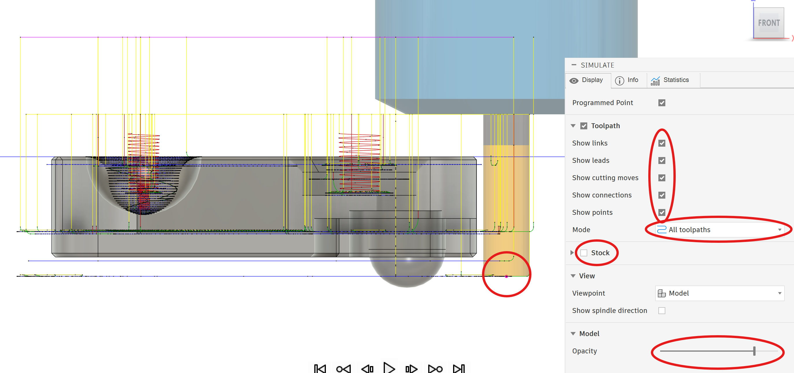
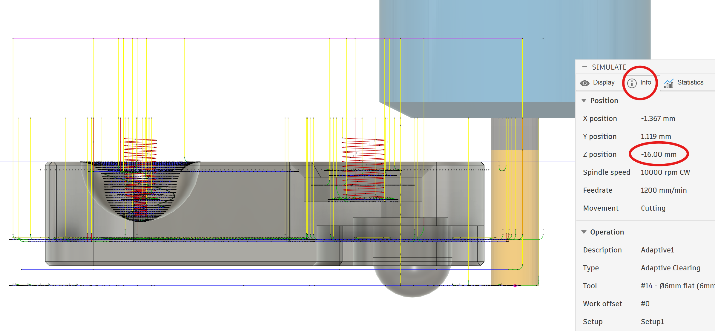
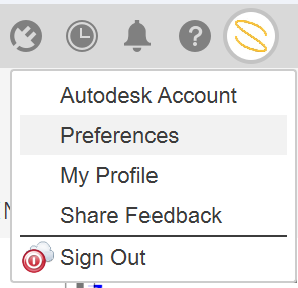
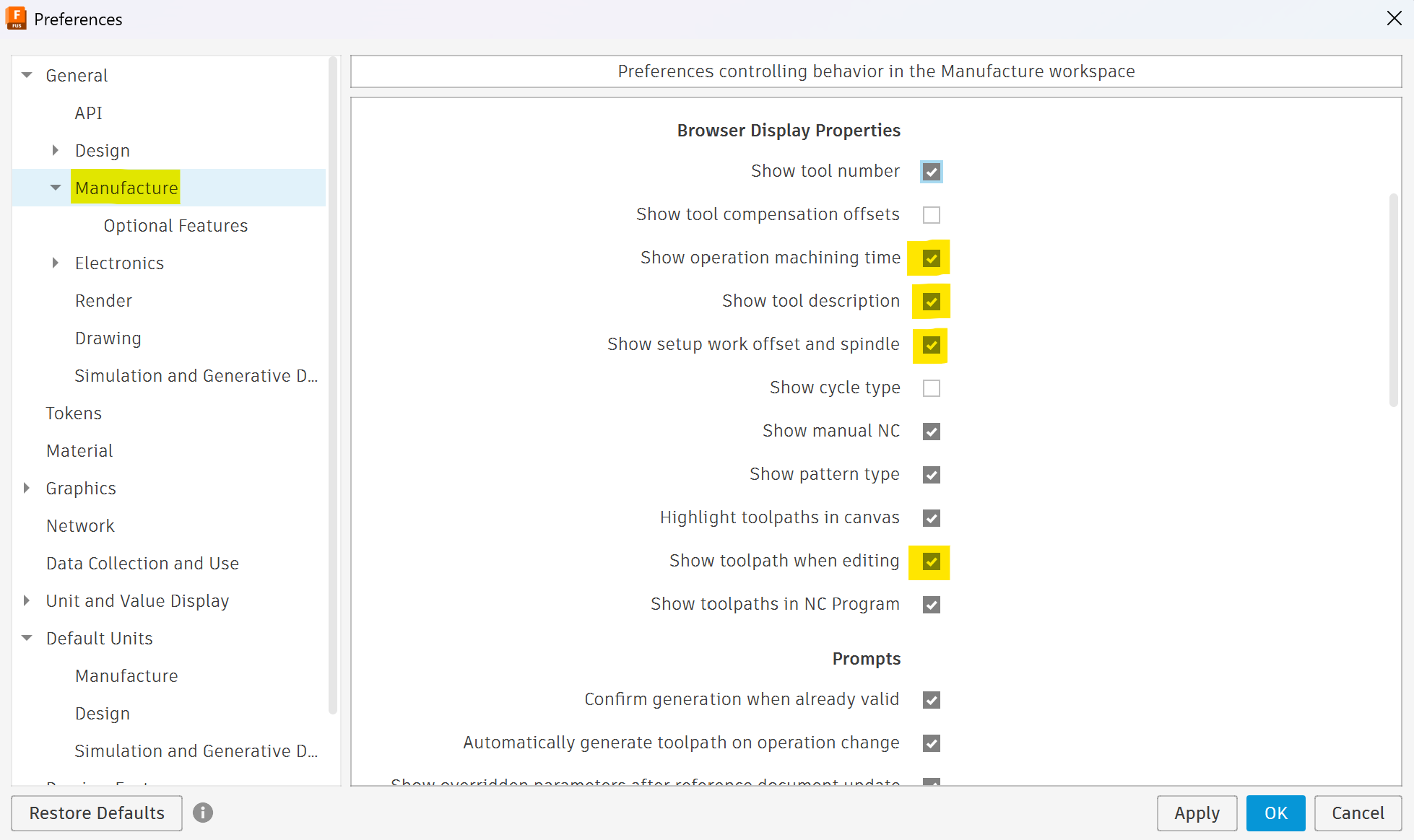
You can display some extra information about your toolpaths from the manufacturing preferences.
CAM patterns
You can create patterns in CAM to repeat a toolpath several times. The most useful patterns are linear, circular or mirror.
Patterns can be used to reduce computation time, increase toolpath efficiency, or reduce the number of operations needed.
There is a setting for operation order which determines how the toolpaths in the pattern are executed. Preserve order does all the operations then moves to the next pattern location. Order by operation does the first operation at every location, then the second operation at every location. Order by tool does every operation with the same tool, then changes tool and proceeds to the next operations.
Linear and circular patterns conserve climb or conventional direction but mirror reverses the cutting direction. One option with mirror patterns is to duplicate the toolpath and set one toolpath to cut in the conventional direction. Then when you mirror the conventional toolpath it becomes climb. If you untick keep original in the mirror pattern only the mirrored toolpath is created.
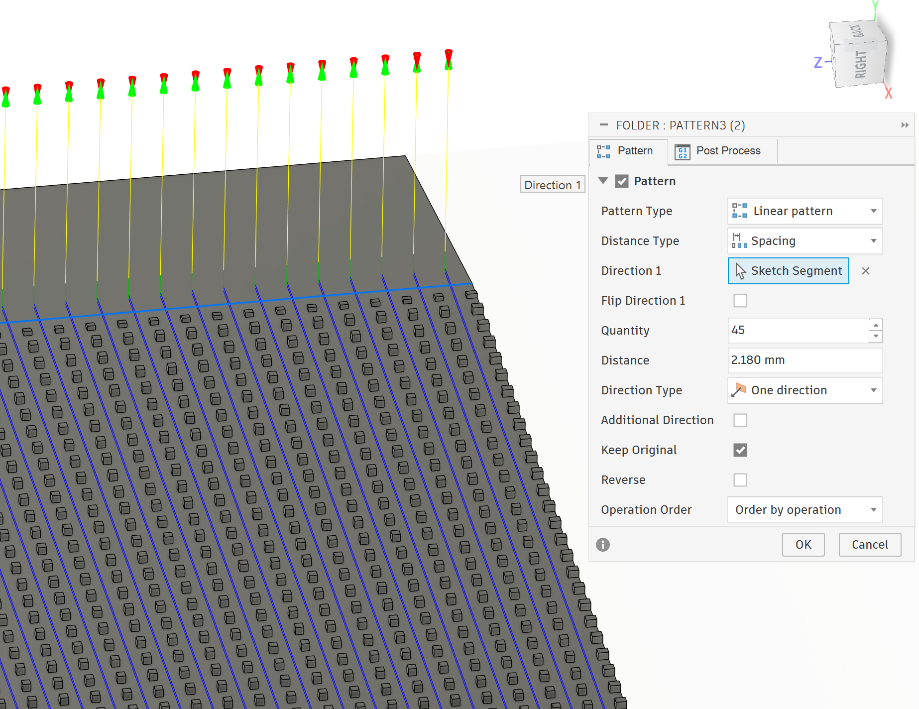
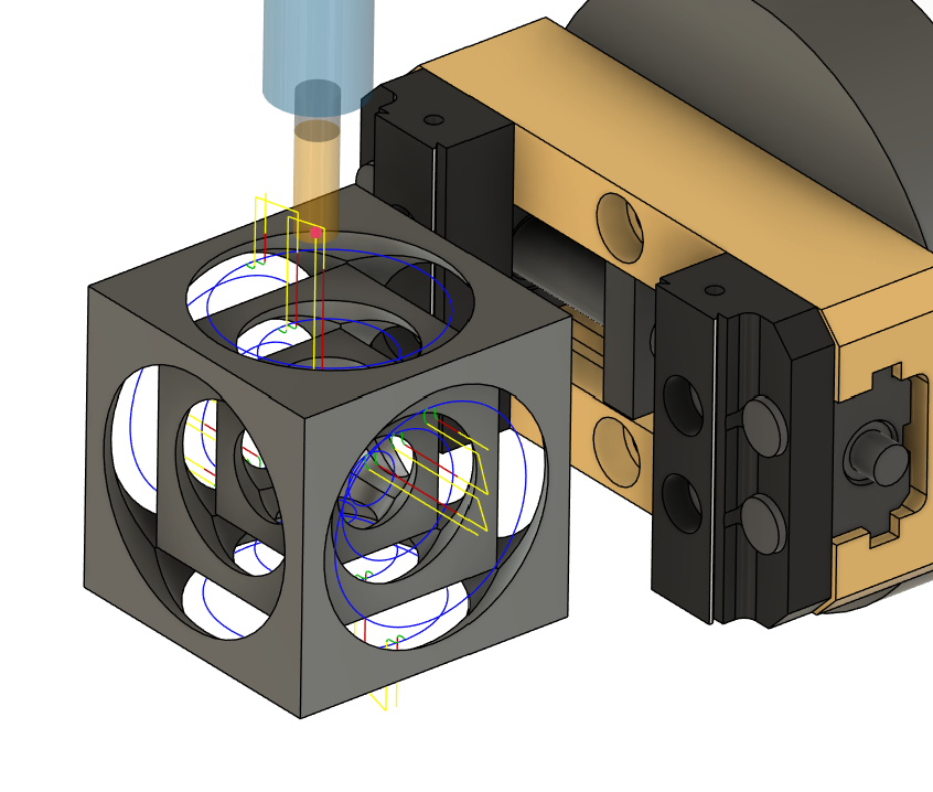
Patterns are particularly useful for 5-axis programming because they can change the tool orientation allowing one operation to machine from different sides.
Manual G-code
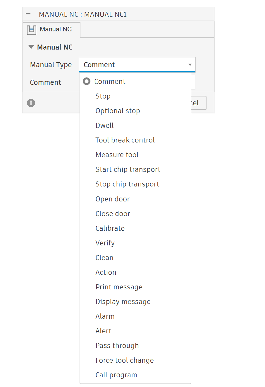
Manual NC is an option under the setup tab that allows for some extra code to be inserted into the program.
The actual code depends on the post processor used: for example the Tool break control option with HAAS G-code creates a G65 P9853 command but with Datron simPL it creates a MeasureToolLength command.
The most useful commands are:
- Comment: allows you to write text into the program that you can read on the machine. Can be used as a reminder to do things.
- Stop: forces the machine to stop and wait for you to press cycle start. This can be useful if you want to take a cut, check if something fits, then take another cut if it doesn't fit.
- Optional stop: the machine will stop and wait for you to press cycle start if you have optional stops enabled on the machine.
- Tool break control: measures the tool to check if it has broken. It will stop the program if there is a breakage or just keep running if the length is similar. This is useful for subsequent operations, drills, tiny tools or if you are running parts with minimal supervision. When running subsequent operations if the first tool breaks then the following tools will also break because they are expecting the first tool to remove a bunch of material. Drills can get pushed into their collet, which is hard to notice because they don't break. Tiny tools can also be hard to notice if they break.
- Pass through: puts whatever you type directly into the program. This is very dangerous, please only do this if you are very experienced and talk to the staff first.
Modeling tool holders
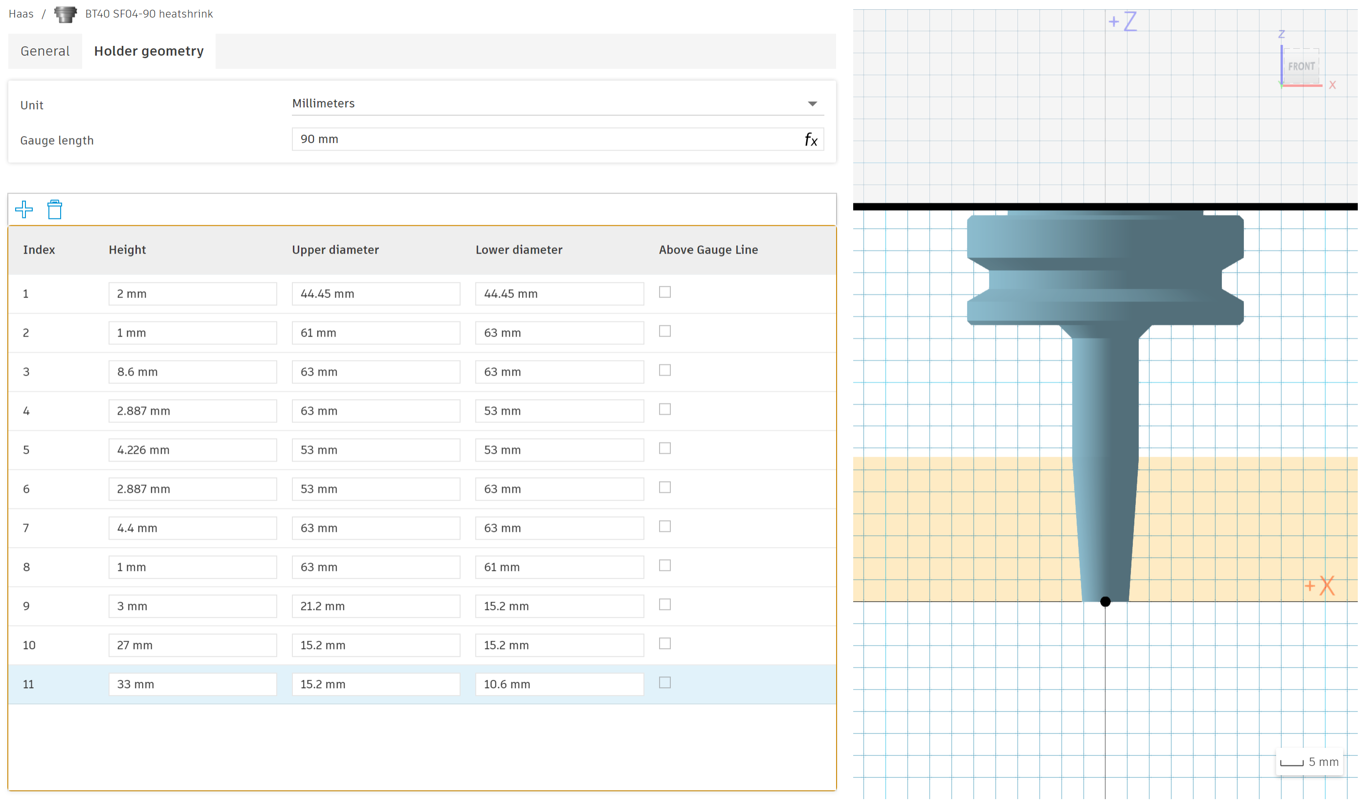
You can model tool holders for your tools. For 3-axis work it is good to use any tool holder so that the simulation detects holder collisions. For 5-axis work is is essential to have correct tool holder models.
An example holder code is BT40 ER20-60. BT stands for British taper and 40 is the size. The BT40 standard determines the top half of the holder that goes into the machine spindle. ER20 is the collet standard and 60 is the gauge length of the holder.
To model tool holders you should start by copying the taper blank model from the Fusion library. Tormach uses BT30 tool holders and HAAS uses BT40.
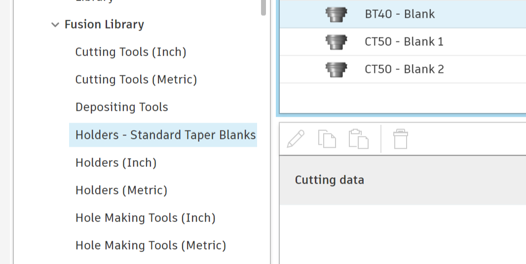
Then you can add sections onto the bottom of the BT40 Blank to match your tool holder. When measuring your tool holder always round up. If you model the holder oversized you will have slightly more clearance than you were expecting. If you accidently model the holder undersized you can collide the holder unexpectedly.
The gauge height of the holder in Fusion should match the gauge height on the holder.
Holder libraries
Modeling work holding
For 3-axis work it isn't essential to model the vice if you keep the tool above the vice and check it on the machine. For 5-axis work it is essential to model the work holding.
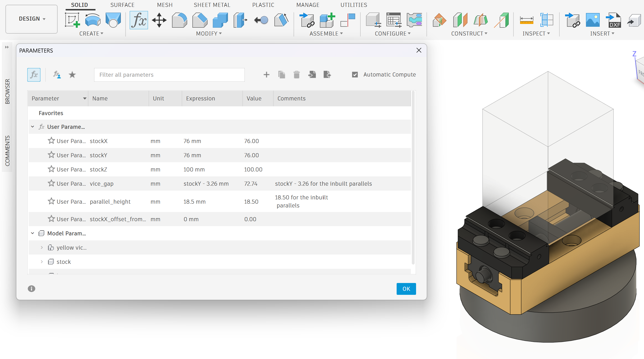
If you search for a vice on the internet you can often find 3D models to use for the most accuracy. Then you can modify the CAD to add parameters and a model of the stock. Using parameters is best because it makes it easy to copy the vice model between parts.
Parametric models
Yellow vice (the small one)
IMG 125-220 vice (the big one)
K11-125 3 jaw chuck (the small one)
NBK-06 3 jaw chuck (the big one)
Machine models
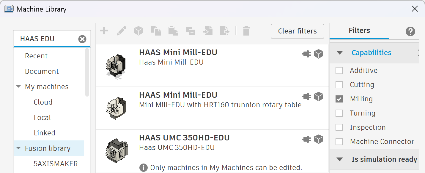
You can download machine models into your machine library from fusions cloud library. These machines can then be added into your setup to make the simulation more accurate, to customise some of the options (e.g. WCS offset) to that machine, and can affect how the code post processes.
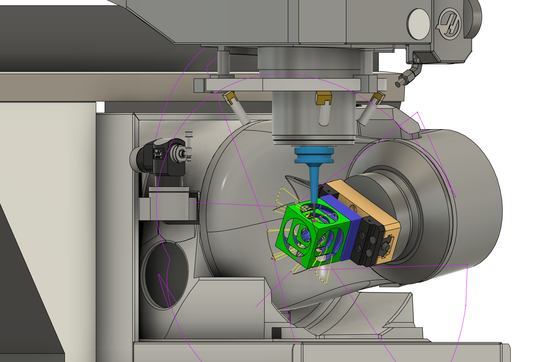
During simulate with machine it will check if the toolpath exceeds the machine axis limits, if there are any machine collisions, and can tell you the tool position relative to the machine zero.
Most of the time machine models are not essential when the work is simple. Machine models are essential when doing any 5-axis work for simulation and to get the correct post processor. Machine models can be helpful with large parts that might exceed the axis limits, and with multiple WCS operations.
You should download the HAAS mini mill model and the Datron Neo model from the Fusion library. However the Haas 5-axis has a zero point fixture which is not on the Fusion library, so you should instead use this model. The 5-axis model is not perfect, it will sometimes show overtravel errors in simulation that don't exist on the machine and the machine can overtravel without the error being detected by simulation.
HAAS 5-axis
Smart versus obedient toolpaths
Smart toolpaths use the remaining stock to calculate a safe and optimised toolpath. They can be harder to control but are typically less likely to crash because they know where the stock is. Adaptive and Pocket clearing operations with rest machining are smart toolpaths
Obedient toolpaths are toolpaths that will do exactly what you tell it. They don't take into account the remaining stock and sometimes don't even use the model geometry. They are great when you know what you want the tool to do, but are more likely to cause a crash when used incorrectly. All finishing toolpaths are obedient, with the best examples being 2D Contour and Trace.
Trim toolpath
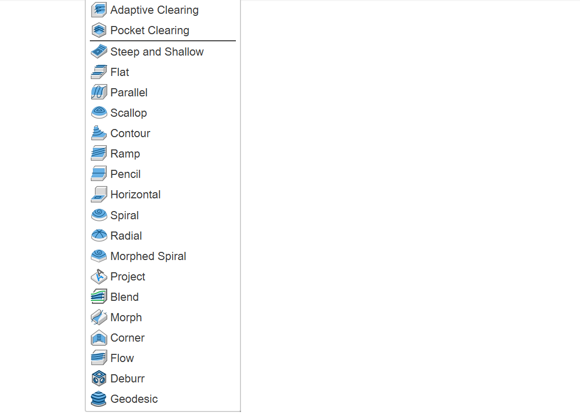
The manufacturing extension give access to the trim toolpath feature, which can be helpful to remove unwanted parts of the toolpath.
Compare and edit
The compare and edit tool lets you change a parameter in many different toolpaths at the same time.
Template library
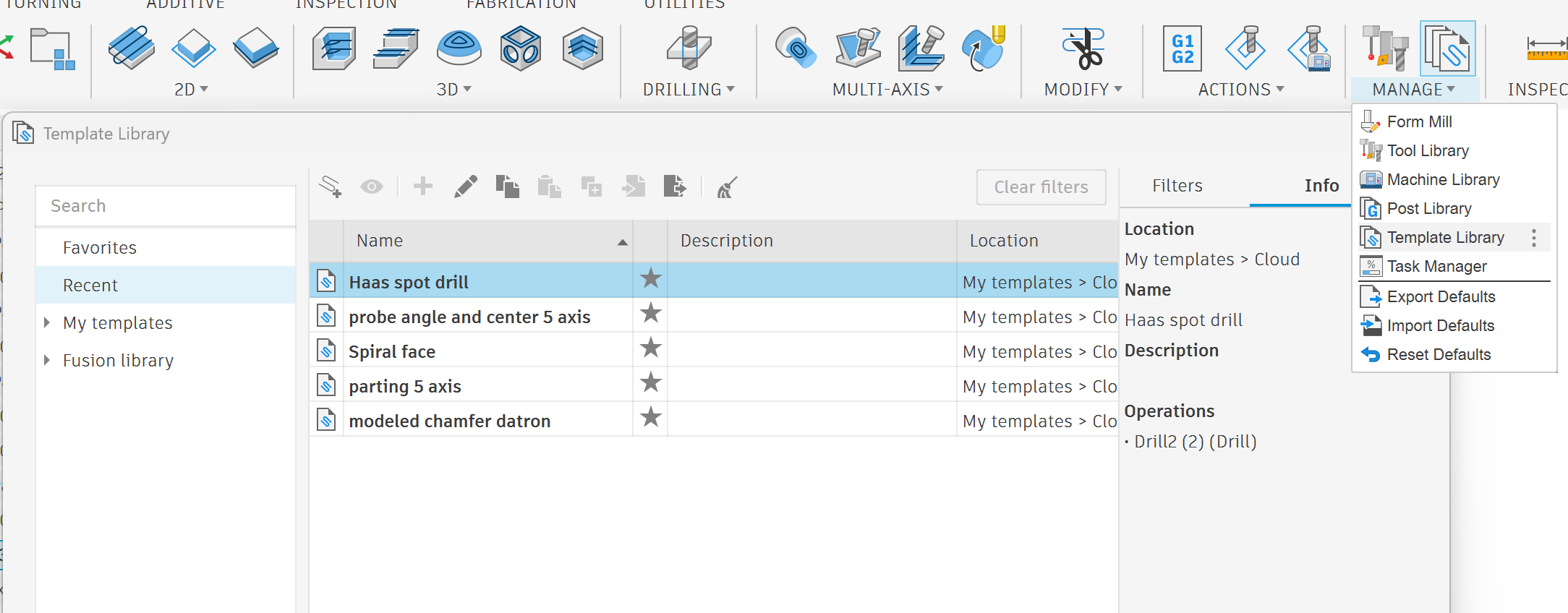
The template library lets you store frequently used toolpaths so you can reuse them quickly. For example a HAAS spot drilling template is useful because it always uses the same tool and goes the same depth.
Multiple work coordinate systems (expert content)
HAAS
Most machines use G54 as the default work coordinate system (WCS) and have additional WCS: G55, G56, G57, G58 and G59. If you want more than these 6 WCS on a HAAS machine you can also use the extended range: G154 P1, G154 P2 ... G154 P99.
If you want to run multiple copies of the same setup you can use the Multiple WCS Offsets setting in the setup, as shown in the video.
If you want to run multiple different toolpaths at the same time you must create multiple setups, each with a different WCS offset. If you haven't selected a machine model in the setup, then WCS offset 1 means G54, WCS offset 2 means G55 etc... Then highlight and post process all the different WCS setups at the same time to make one big program with multiple WCS.
Datron
The Datron uses an unnamed temporarily stored WCS by default. If you want to save a WCS you can create a named WCS and then save the current WCS into the named WCS. When naming your WCS on Datron you can use numbers and letters but Fusion can only create WCS numbers.
If you want to run multiple execution of the same part Datron explains how to in this article.
If you want to run multiple different parts at the same time you can call different programs from a main program, as shown in the video.
Alternatively, you can make each setup in Fusion with a different non-zero WCS offset (1,2,3) and create matching WCS names on the Datron. The WCS names on the Datron must be numbers because Fusion can't create a WCS with letters.