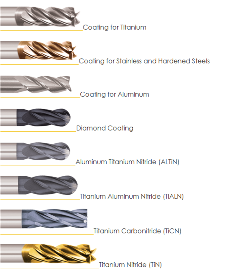
UNSW Making

Advanced CNC Milling: Tooling

Tool setup


Essential content

ER tool holders

ER collets are the most common collet in Kirby because they are simple to use and can fit a wide size range. However they are not the most high performance collets.

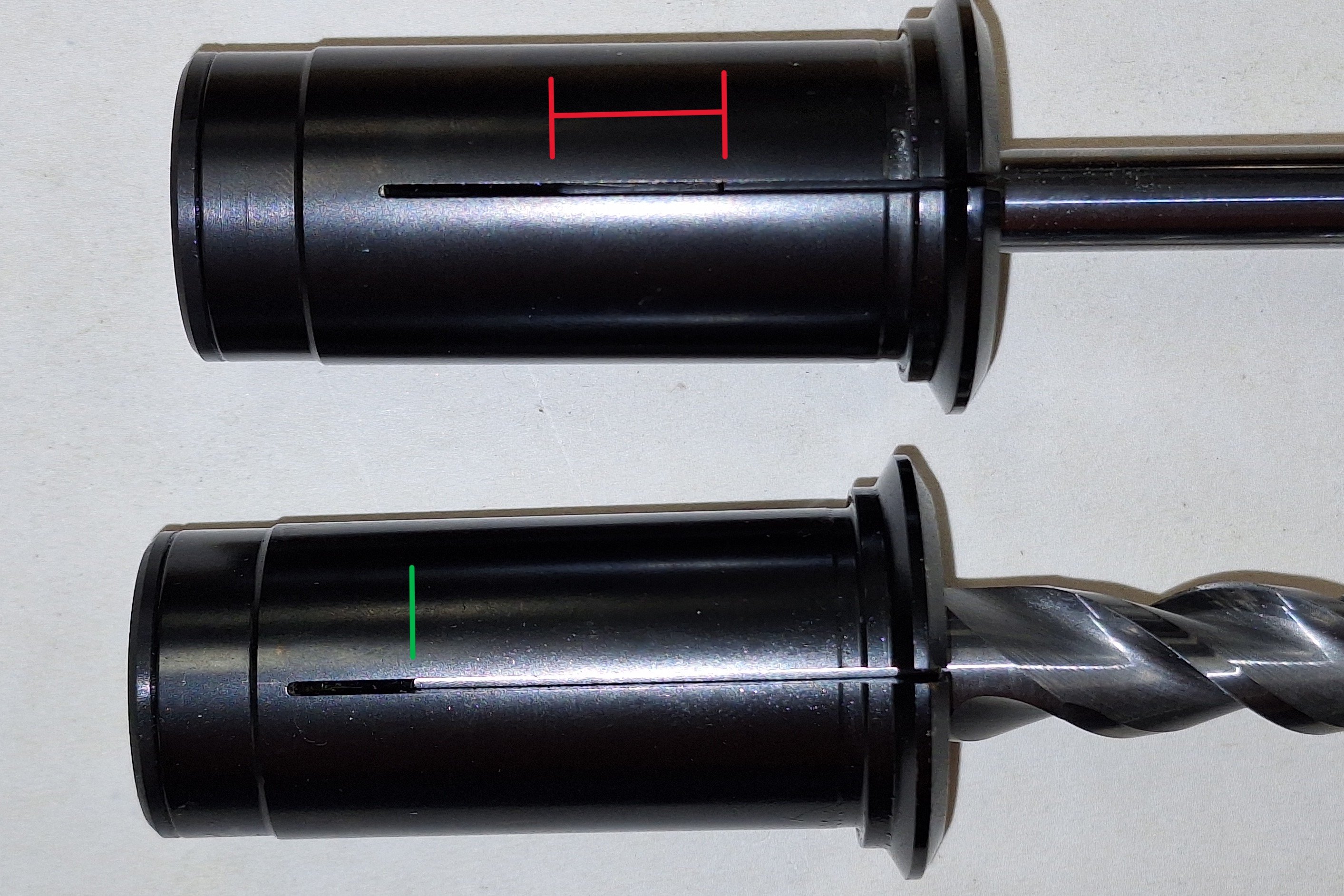
Some ER collets are designed to be used with through tool coolant and have O-rings or shorter grooves that prevent coolant flow through the collet. These are used for thru coolant drills, where you want all the coolant pressure to go through the drill.

ER collets are not designed for coolant flow through the collet so if you turn on through spindle coolant it gets sprayed in a cone, mostly away from the tool. This isn't ideal but spraying coolant through the ER collet can still work and is helpful in certain situations such as drilling and deep cuts with an endmill.

When using ER collets up make sure to clean everything and fill 80% of the collet with tool.
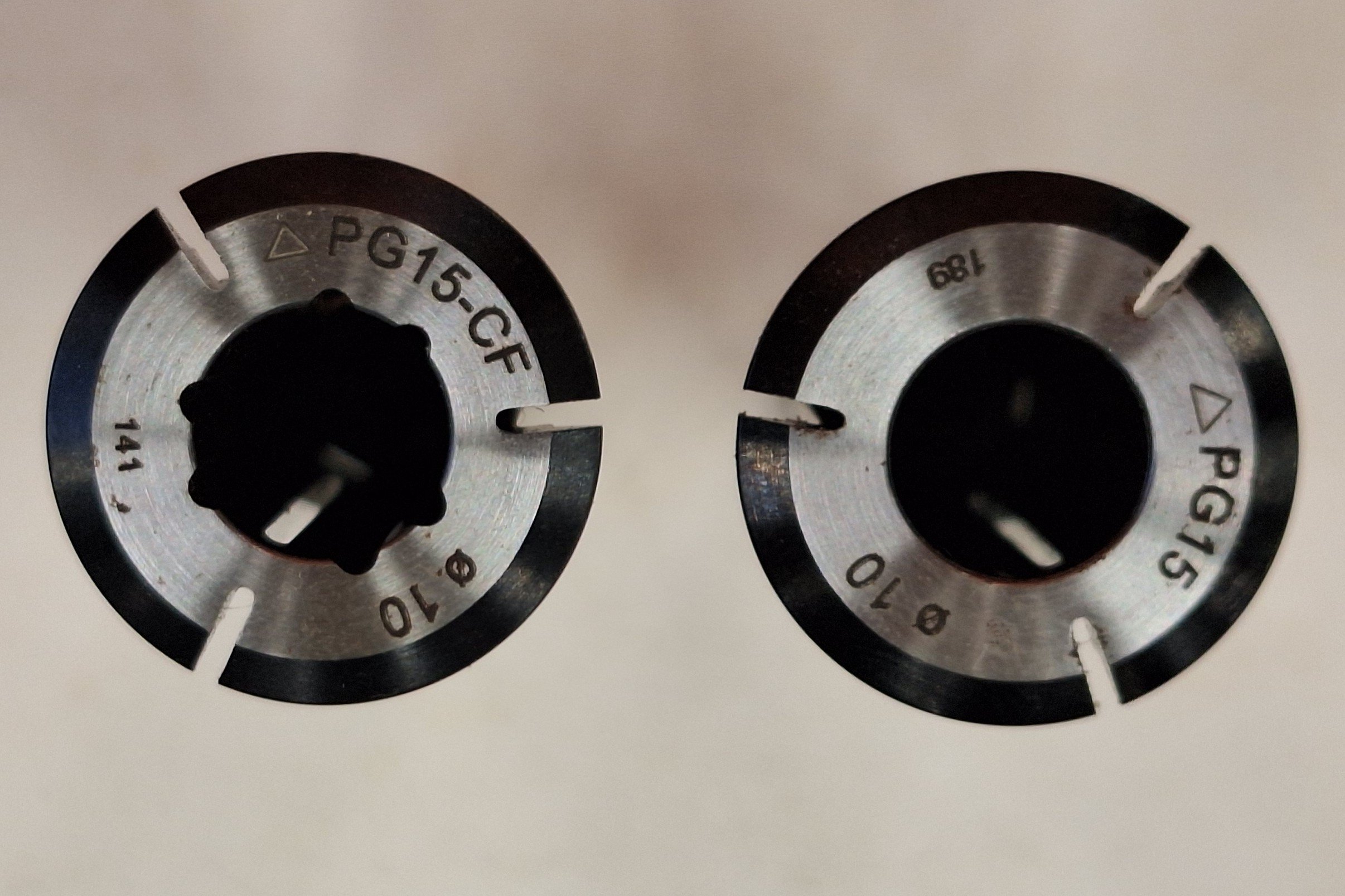
PG tool holders

PG collets have better runout and clamping force than ER collets but they can only fit exact sizes of endmill and cannot be used with drills.

Some PG collets also have extra grooves on the inner bore to allow thru collet coolant. This is an excellent feature for clearing chips, especially in deep or tight pockets.

If you are using a thru coolant drill don't use a thru coolant collet because you want all the pressure to go through the drill.

20260323_173603

When using these holders it is important to put the shank deep into the collet to prevent damage to the holder. When the hydraulic press presses the tool in it creates a large radial force on the collet, which if unsupported by a tool inside can bend part of the collet.

If the tool is not deep enough in the PG collet, thru spindle coolant can flow through the grooves which is not ideal.

If you need more stickout, use smaller collets or small ER collets.

20260323_173316 edit

DC tool holders

These are used on the 5-axis because they are small diameter holders and can be quite long, which is useful to create clearance between the holder and part or vice.

Unfortunately the smaller diameters and larger length makes them less rigid and they will vibrate more. For tips on preventing vibration go to the machinist essentials learn page.

Heat shrink tool holders

Heat shrink holders have similar or slightly better runout and grip strength to PG collets. These holders can only be used with exact size tools and are more difficult and dangerous to setup.

Coatings


Essential content

Why use coatings

  1. Increase the surface hardness for cutting hard materials
  2. Increase heat resistance
  3. Increase the toughness to increase tool life
  4. Increase lubricity which reduces friction, cutting force and heat generation

Coatings decrease tool sharpness because they add material evenly to create a radius on the cutting edge, which has good and bad effects. Coating increase the strength of the cutting edge because perfectly sharp tools are more fragile and can break easily in hard materials. However blunt is not good either, so thinner coatings are typically better.

Coating tools increases the chance of rubbing because the cutting edge has a larger radius. This is why uncoated tools are most commonly used in aluminium: they are sharper and rub less. Some coatings (DLC) can be used to cut aluminium, and these coatings are typically very thin (0.5 - 2.5 um) to maintain sharpness and increase the lubricity of the tool to prevent built up edge and chip welding. Most coatings for cutting steel should not be used with aluminum because they are not sharp enough and often stick to aluminum (especially if the coating contains aluminium).

Which coating to use

Tool coating chart

1712911720888174
DLC coating for aluminium

Dimond like coating (DLC) for aluminium

Tool deflection


Expert content

When a tool contacts material the cutting force causes the tool to bend. This is obviously undesirable, and there are several things you can do to minimize deflection:

  • Larger diameter: Tool stiffness is proportional to diameter to the power of 4. So double diameter is 16 times stiffer.
  • Less stickout: Tool stiffness is proportional to length to the power of 3. So half the stickout is 8 times stiffer.
  • Larger / more rigid tool holder: Bigger diameter and shorter holders also increase stiffness.
  • Less cutting force: Decrease the stepover is the best way to reduce cutting force. Decreasing stepdown can also reduce the force, but can increase vibration. Decreasing feed rate can reduce the cutting force but can cause rubbing if too slow, which actually increases cutting force because the tool isn't cutting.
  • Repeat finishing pass / spring pass: repeating the final cut helps to remove the taper on the walls because cutting force is very low. However this can be problematic in materials that work harden such as stainless steels.
  • Fewer flute tools: Less flutes means less contact and less force. However, fewer flutes can also increase vibration.
  • Higher helix angles: increase shearing and changes the direction of the cutting forces to be more axial and less radial.
Deflection-of-milling-tool-at-the-bottom-of-the-workpiece-edge-Adapted-and-reprinted

Specific tools

Drills (essential content)

Drilling is the second fastest way to remove material (behind a saw). You should use drills as much as possible, especially in hard materials. Use them to pre-drill into pockets to avoid ramping because ramping is very hard on the corners of tools.

Bull nose endmills (essential content)

Bull nose endmills have small corner radii and a flat bottom. You probably know from experience that the most fragile part of flat endmills is the corners. This is because the corner has the least support material behind it and can experiences both radial and axial cutting forces at the same time.

Bull nose endmills eliminate the weak corner, so they are stronger and last longer. They are most applicable to cutting harder ferrous materials and should always be preferred when ramping is required in ferrous materials. Bull nose endmills can be used for roughing, then a flat endmill for finishing.

Bull-Nose-Cnc-Milling-Cutter

Thread mills (essential content)

It is important to know the diameter of your thread mill, but it can vary between different brands. Try to find the information on the manufacture's website or use diameter probing on a HAAS.

Choose a gentle feed per tooth. It can be helpful to choose a feed per tooth appropriate for the thinnest part of the thread mill. For example a M8 thread mill has a cutting tip diameter close to 6mm, but the shaft is 4mm. So choose a feed per tooth appropriate for a 4mm cutter, because that is the weakest part of the tool. Typical feed per tooth would be between 0.01mm - 0.035mm per tooth.

When threading holes the center of the tool travels a small diameter spiral, but the tip of the tool traces a path several times longer. This means that the actual feed per tooth is much larger than the programed feedrate. To fix this problem you need to reduce the feed per tooth by the effective feed rate factor, which can be calculated here. If you are cutting an external thread you need to do the opposite and increase your feedrate. In your tool library always set up your thread mills with slow internal and fast external thread cutting profiles. There is more information about effective feedrate compensation in the feeds and speeds module.

Doing multiple passes can reduce the risk of breaking a tool, 2-3 passes is typically safe. To make the stepovers evenly spaced you can copy the formula:

pitchDiameterOffset/(numberOfStepovers *2).

Cutting a correctly sized thread can be difficult because there are a lot of variables that affect it's size. If you are unsure start with an undersized Pitch Diameter Offset, and gradually increase it. Theoretically, Pitch Diameter Offset should equal the Thread Pitch but can vary due to how the thread mill has been cut and inaccuracies in the diameter.

Reamers (expert content)

Reamers are used to make precision holes.

Backside chamfer (expert content)

Backside chamfer tools can help reduce the number of setups required by chamfering the backside of a part.

Related Badges

Categories: Manufacturing