Getting Access to the Laser Cutters


Intro to Laser Cutting
_____________________________
_____________________________

FDM or fused deposition modeling, is a material extrusion method of additive manufacturing where plastic filament is pushed through a heated nozzle, which melts the material and deposits it in 2D layers on the build platform. While still warm, these layers fuse with each other to eventually create a three-dimensional part.
If you want to know more, we have information about settings and slicing your own models in our 3D Printing Basics Page!

The fleet of printers we across the UNSW Makerspace Network the Bambu Labs P1S, X1C and X1E's!
Whether you are a CAD modelling wizard or just starting on your journey to modelling, Fusion 360 is a great CAD software with a full array of capabilities from design to manufacture! Whilst we will be focusing on creating parts for 3D printing in this section, there are a range of resources that can help you in other aspects of using this great software over on the AutoDesk Website.
So what does 'Slicing' mean? Slicing means converting the 3D model file into a machine language that can be recognized by the printer, and the printer can only print successfully after recognizing this machine language. This machine language is called the G-Code.
You do not need to slice your own files to send them to our 3D Printing hub, but if you'd like to learn more about the slicing software we use you can check out the learn page below!
To get something made, you can send us your file through our 3D printing hub. Whilst we ask that you send us the STL file and then we do the slicing for you, downloading slicing software yourself and playing around with slicing your file is a great way to get familiar with the process. This will also give you an idea if your file is going to print successfully (view it in 'preview' mode), and will give you a print time estimate (when you click 'slice'). If you have a preference for any settings you discover, write it to us in the notes!
________________________________________________
_________________________________________________________

Supports structures are undesirable features that increase print time and produce plastic waste. Additionally, they have the potential to ruin the surfaces of prints, leading to more post-processing time.
In the end, it’s not always possible to completely avoid support structures, but we can try to minimize them as much as possible.
As a first rule of thumb, we should always consider model orientation when designing parts – that is, how parts will be positioned during printing. This should, among other things, try to eliminate overhangs and bridges, or at least reduce them to a minimum.
Secondly, think about how splitting your model could help reduce the need for supports. In the above instance, could the wheels of the car be printed separately and joined again after?

Bed adhesion is one of the major sources of failure in 3D prints, and printing this model could prove to be a headache. When 3D prints don’t stay in place on the build plate, you can get curled, shifted, potentially disastrous results.
The amount of surface area contacting the bed is a very important factor in its ability to stick. Think of ways in which you could increase the surface of your model that is touching the bed, could you create a little flat surface on the bottom of a curved part?

Another good tactic for reducing build time and filament wastage is removing unnecessary material from models. For functional parts, this can be more complex due to the direct impact of that material on the overall resistance of parts. For more aesthetic models, however, there’s less to worry about.
Chamfers and fillets are great tools for removing material while at the same time smoothing sharp corners and edges. Yet, there are other ways, too.
For the above example, we could save some filament by removing material from the vehicle’s underside. This region should stay hidden most of the time, anyway. How could you reduce material in your models?

Small-sized features are not always able to be printed successfully. As a general rule we usually suggest features no smaller than 2mm. While this kind of issue is often detected during the model slicing, it’s good to think about it while still in the design stage and not waste time going back-and-forth between CAD and slicer.
The “Measure” tool can be an excellent ally for checking the printability of fine details. Let’s take, for example, the frame of our vehicle’s windshield. This should be the finest detail of the model, and it will definitely present a problem if we scale down the entire model during slicing.
Make sure to check all the measurements of your parts before sending them to us, if it's too small, we won't be able to print it!
When making something, you will most likely need fasteners to attach various parts and materials together. These are some common ones!


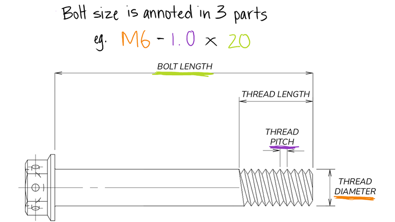

Common screw head types found in the makerspace
Available lengths: 15mm, 25mm, 30mm, 40mm, 50mm, 55mm, 65mm
Screws require a clearance hole, and a pilot hole. Clearance is larger than the threads and pilot is smaller, so that the screw will grab into the bottom material and clamp the material together.

There are various different screw and bolt heads for different applications, but here are some common ones!
Common bolt heads in Makerspace:
Common screw heads in Makerspace:

Drivers are the tool or bits used to 'drive' the screw into the materials (as in screwdriver).
There are a few types of driver heads, dependent on the slot shape on the head of the screw. Here are some commonly found ones.
Common driver types that are available:


The Good
The Bad
The Good
The Bad
The Good
The Bad
The Good
The Bad
Common types of tapes found in makerspaces: electrical tape, masking tape, duct tape
What surfaces do you want to join and will a mechanical or chemical join be best?

Uses:
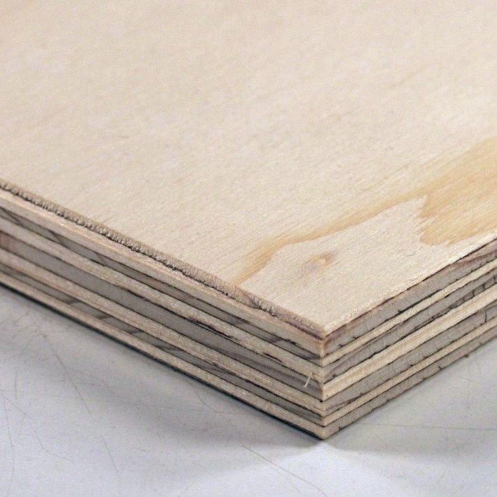
Laser Cutting + general woodworking
Source:
Shop or offcut bins in Kirby or Squarehouse (DFL)
Bunnings (Must be Interior Ply)
Sustainability:
Not great...
Uses:
General woodworking
Source:
Bunnings
Sustainability:
Not great...

Uses:
General woodworking
Source:
Wherever you can find it (Make sure to remove all nails and screws!)
Sustainability:
Better...Good to give things a second life!

Uses:
Laser Cutting (best), drilling, bandsawing, sanding, melting
Source:
Shop or offcut bins in Kirby or Squarehouse (DFL)
Art supply stores (Kadmium)
Sustainability:
Average...but we can recycle it! Make sure to add it to our dedicated acrylic recycling bins

Uses:
Great for use with the woodworking tools
Source:
Recycling bins (make sure you know what type of plastic it is)
Melt it at home (SAFELY...) or chat to Staff at the DFL
Sustainability:
Great...we love giving things a second chance

Uses:
Light-weight frames and submarines. Cut using specific cutter, ask a staff member, we have plenty.
Source:
Bunnings
Sustainability:
Terrible...definitely contributing to the end of the world

Uses:
Easy to work with, can be folded, drilled and cut
Source:
Have a look in the Kirby offcut storage
Sustainability:
Pretty good, just don't chuck it in the general waste bin please

Uses:
Very difficult to work with...avoid if possible
Source:
Steel suppliers
Sustainability:
Actually not too bad if you do the right thing with it

Uses:
So easy to work with, great for fast prototyping! Can be cut by hand, in a laser cutter or on the bandsaws.
Source:
Too many places to list, try a recycling bin to start with!
Sustainability:
Excellent

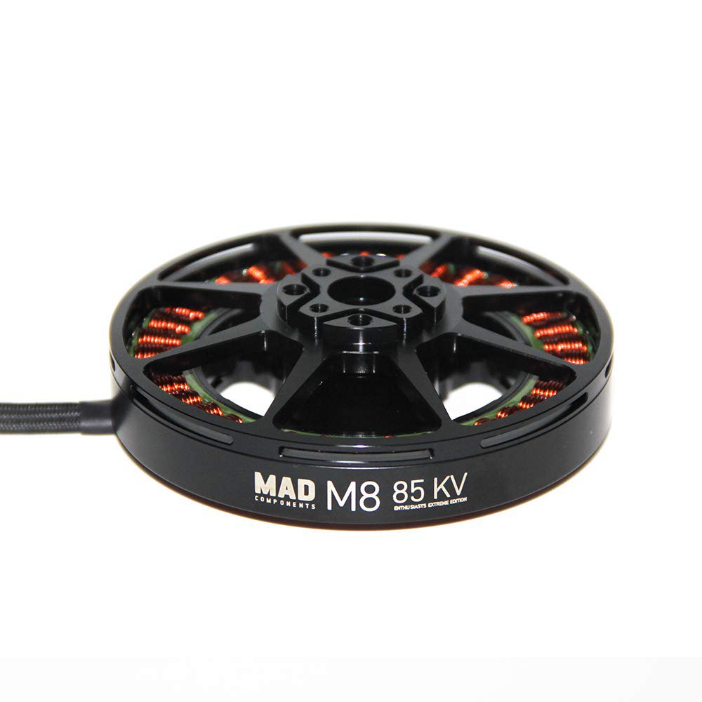
Brushed
Brushless


Servo Motors, (usually just servos!) are used when you need to rotate to specific angles but are slower and higher torque than DC motors. There is a built-in feedback loop system that allows the servo precisely move to your desired angles (usually between 0-180°).
For continuous movement, you can find continuous rotary servos, which work in a similar fashion, without the potentiometer.
To control a servo, a servo horn can be used to link it up mechanically.


Typically used for aeroplanes and low load applications. Not suited for any application where a significant load is required to be lifted.

Useful for small scale robotic projects which require a heavier item to be lifted.

Stepper motors are precise electric motors using a four-wire configuration to control internal coils. Electrical pulses sent through these wires in a sequence rotate the motor in discrete steps, enabling precise positioning and speed control
With the inrunner design, and the ability to hold position even when stationary makes these motors ideal for applications such as 3D printing, CNC machining and robotics.
Control with a dedicated motor controller is required to generate precise pulses for control of the steppers. Steppers don't typically have position feedback, but encoders can be added.


Linear actuators converts rotary motion to linear motion for precise position control, often incorporating feedback mechanisms. They offer high force but slower speeds.
The term 'stroke length' indicates the maximum extension distance. Mounting may require rotation, achieved with clevis or trunnion brackets designed for positioning.
Now you've got rotation from your motors, how do you make it useful?
Typically, you will use gears to change the speed and torque of your motor, an axle to transfer that rotation to your wheels, and bearing or bushings to keep the axle supported and rotating smoothly.
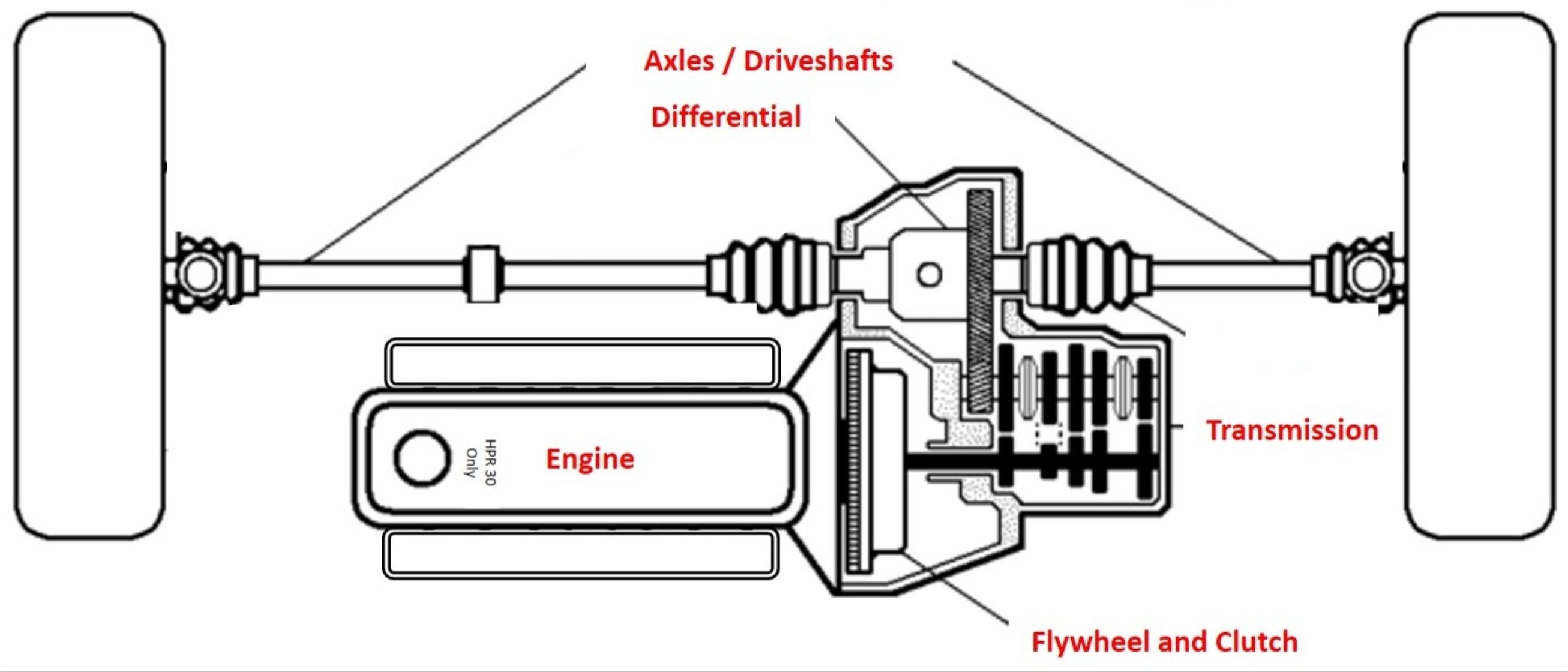
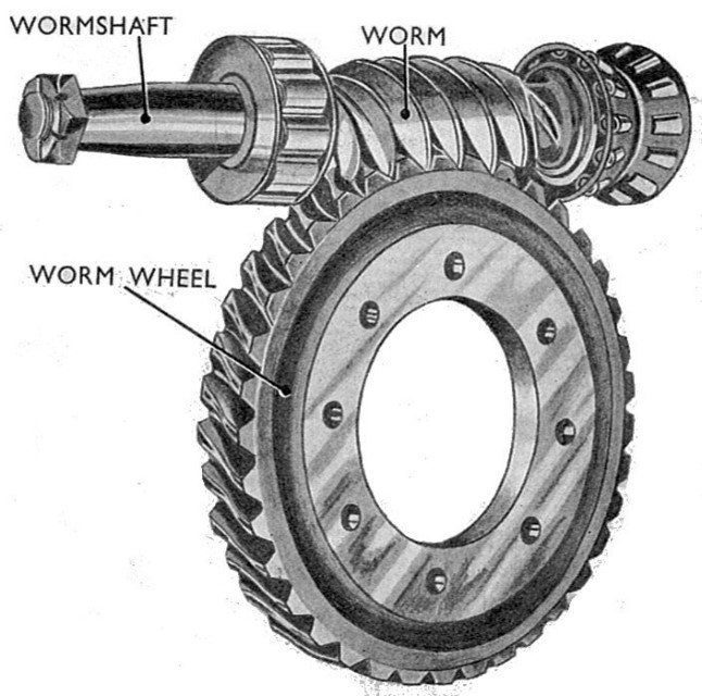
Gearboxes are mechanical devices that are used to transmit and control the speed, torque (rotational force), and direction of rotation in various machines and systems.
For these applications they are usually used to increase the torque of the motor while decreasing the speed. Different types of gearboxes have advantages such as size, efficiency, complexity, cost and ability to backdrive the motor.
The Good:
The Bad:

The Good:
The Bad:

The Good:
The Bad:
To make your own laser cut gears, we recommend using an Online Gear Generator
If you want to know more about how gears and gear ratios are calculated to change speed and torque, here's a lovely video from 1936.

Now that you've geared your motor to an appropriate speed and torque, you'll need to transfer that rotation to your wheels! The best way is through an axle that's supported by bearings or bushings.
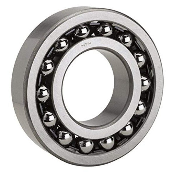
Bearings have small ball bearings to assists in rotation. The inner ring rotates with your shaft as it rolls along.
The Good:
The Bad:

Basically, a bushings fills up the space between your housing and the axle while providing less friction.
The Good:
The Bad:

It's a stick that transfer your rotation. Ideally fits into your bearings and bushings so you can support them.
This can be a range of materials for DESN1000. From fibreglass rods, to steel shafts and chopsticks - just make sure it doesn't have too much friction.
Depending your axle profile you will need to secure your gears or bushings onto it. The shaft you see in the picture above, is a D shaft. To secure this, we use a coupling!

Another very good way of transferring rotation from a shaft or motor to a wheel is the use of belts. With the scale of your projects, a 'belt' can just be a rubber band!
With belts, ensure that they cannot slip from their wheels, and ensure they are in tension and they should work well.
In engineering systems, the most common way of attaching an axle to a motor shaft is some sort of coupling. Shafts are inserted either side, and clamped together with two grub screws.
For more information please check here: Arduino Basics Module

Powering Arduinos!
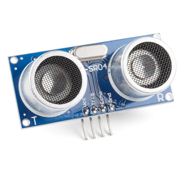
Uses ultrasonic sound waves, sends a pulse, and receives the echo. Calculates distance from the time delay. Great at sensing things at medium range.
The Good: Can sense all material types, even see through objects,
The Bad: Struggles with thin, curved or soft objects that absorb/deflect ultrasonic waves.

Content for this module in the infrared range (wavelength between 760nm to 1mm) to transmit data or find ranges. Infrared radiation is transmitted and bounces off objects before being picked up by the receiver.
Can also be used as a means of sending data.
The Good: Line of sight, no reliance on visible light, good for objects between 10mm to 800mm
The Bad: Ineffective at longer ranges, low data transmission rate, affected by particles such as dust or smoke.
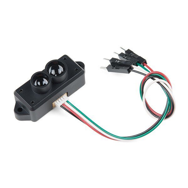
Rather than Radar (Radio Detection And Ranging), we have Lidar (Light Detection And Ranging)
Send pulses of lasers and measures their echoes reflecting back from objects similar to ultrasonic sensors.
The Good: Not light dependent, better at detecting smaller objects compared to Radar, smaller beam spread than Ultrasonic.
The Bad: Expensive, doesn’t register see-through materials (lights passes through transparent obstacles!)

Sensor for measuring linear force/acceleration.
Most accelerometers will give you three axes of measurement
The Good: Measuring acceleration and deceleration, typically gives X,Y,Z axis readouts.
The Bad: Gives you acceleration, NOT velocity. Tells you if you're speeding up or slowing down but not how fast you're going.

Sensor for measuring angular rotation
Gives three axes of rotation, pitch, roll, yaw.
The Good: Measuring angular velocity (not acceleration, although you can calculate acceleration yourself)
The Bad: only provides angular velocity, not acceleration nor linear velocity.

Consists of Gyroscope and Accelerometers (and sometimes, magnetometers)
Best of both worlds!

Uses a camera and computer vision algorithms as a sensor to find objects. Everyone's got a camera (sometimes a few now) on their phone so we're not going to explain that here..
The Good: Able to identify colours and signs using computer vision to identify obstacles
The Bad: No range sensing, doesn’t work as well in low light, expensive in price and computing power.

There are an assortment of other sensors that are compatible with Arduinos or Raspberry Pi's. We can't cover them all here, but if you look up the manual from the suppliers, they will show you how to use them - sometimes with example code!
Some examples are:

If you need something quick - we suggest going to Jaycar as they have in-person stores.
The closest ones are:
Jaycar Sydney City
Jaycar Alexandria
Jaycar Queens Park
Otherwise Core Electronics and RS Components do quick shopping for their online stores!
In a pinch, Amazon next day delivery is also quite good!
Some tips and tricks on how to get good connections!
Breadboards are commonly used prototyping boards with the following layout.

If you want can, it's usually worth it to buy a set of prototyping jumper wires like that are pre-cut and bent to fit in a breadboard.

Breadboards are great for prototyping, but once you've finalised your design, it's much safer to move it to a more reliable solution. E.g. Solderable Breadboard/Veroboard/Protoboards
Which of these do you prefer to work on?


Crimps are mechanical connections that get squeezed or crimped onto the ends of stripped electrical cables to ensure a strong connection.
There are many shapes and sizes of crimps, the colour of the plastic (usually red, blue and yellow) are for different gauge of wires.

When using crimps, you should use a crimping tool, and ensure that the crimps are secured tightly, but not overly tight.

Connectors and terminal blocks are another great way of connecting wires. Terminal block are typically used soldered onto PCB's to provide a stronger connection (it's screwed in to compress the wire!)
There are also various different connectors like WAGO connectors that are a little more expensive, but are great at connecting wires quickly. It even works with different gauge of wires using the same connector!
Last but not least, we have a T-splice connector, which are usually used to split a single connection into two!


Seen as one of the strongest connections, but also the hardest one to do well! There is an art to soldering, and if you're interested, we run an induction for teaching basic soldering here!
Soldering is the process of joining metal parts by melting a metal alloy (solder) to bond them together.